EP3240144
[0011] Figure 2 illustrates a cross-section of a synchronous reluctance electric machine 20 according to an embodiment of the present invention.
【0014】
図2は、本発明の一実施形態による、同期リラクタンス電気機械20の断面を示している。
The machine comprises a stator 22 including a stator yoke 24 and multiple stator teeth 26.
機械は、ステータヨーク24と、複数のステータティース26とを含むステータ22を含む。
Windings 28 are wrapped around the stator teeth 26. In one embodiment, the windings 28 are fractional slot concentrated windings.
巻線28は、ステータティース26に巻き付けられている。一実施形態では、巻線28は、分数スロット集中巻線である。
Each pair of diametrically opposite stator teeth 26 is connected is series or parallel to form an independent phase winding of the synchronous reluctance machine 20. In an exemplary embodiment, the synchronous reluctance machine 20 has a three phase winding.
直径方向に対向するステータティース26の各対は、直列または並列に接続され、同期リラクタンス機械20の独立位相巻線を形成する。例示的な実施形態では、同期リラクタンス機械20は、三相巻線を有する。
[0012] The synchronous reluctance machine 20 also includes a rotor 30 having a rotor core 32 and concentric with the stator 22.
【0015】
同期リラクタンス機械20はまた、ロータコア32を有し、ステータ22と同心のロータ30を含む。
The rotor core 32 may include multiple laminated sheets disposed on top of each other, or may be formed as a single piece.
ロータコア32は、互いに重ね合わせて配置された複数の積層シートを含んでもよいし、一体的に形成されてもよい。
The rotor 30 also includes rotor poles 34 which comprise multiple ferromagnetic regions and non-ferromagnetic regions formed of a single material and are selectively formed so as to enhance a synchronous component reluctance torque and reduce a contribution of undesirable harmonic components of magnetic flux generated by the windings 28.
ロータ30はまた、単一の材料で形成された複数の強磁性領域および非強磁性領域を含み、同期成分リラクタンストルクを増強し、かつ、巻線28よって生成される磁束の望ましくない高調波成分の寄与を低減するように選択的に形成されるロータ極34を含む。
The synchronous reluctance machine 20 distinguishes from a permanent magnet machine by not having windings on the rotor teeth and not having permanent magnets embedded in either the rotor or stator teeth.
同期リラクタンス機械20は、ロータティースに巻線を設けず、かつロータティースまたはステータティースに永久磁石を埋め込まないことによって、永久磁石機械と区別される。
US2012153764
[0020] In FIG. 3 they are schematically represented: a stator 1, a winding(*単数)2, permanent magnets 3 radially located inside the rotor 4.
【0016】
ロータ4に配置されたステータ1、巻き線2、永久磁石3が図2において模式的に図示されている。
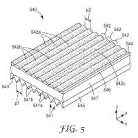
The lateral surface of the rotor 4 is provided with undulated protuberances 42 axially extended in the active part of the said surface.
ロータ4の側面には、その面の活性部において軸方向に延在するうねった突起群42が設けられている。
Active part of the lateral surface means the surface facing the winding 2. Depending of the position of the rotor the value of the inductance will vary for each electrical phase as previously explained.
側面の活動部は、巻き線2に面した面を意味している。ロータの位置に依存して、すでに説明したように、インダクタンス値は各々の電気的位相に関して変化する。




※コメント投稿者のブログIDはブログ作成者のみに通知されます