


US6025860
"Hot stamping of metallic foils has been widely used for decorating, with graphics and text, such items as book covers, wallets, attache cases, handbags, and suitcases. These articles are made of leathers, vinyls or textiles, which have surfaces with deep grains or fibers having valleys, for example, 0.001 inches or even 0.003 inches in depth. For decorating purposes, the metallic foil, transferred by heat and high pressure, typically has a mirror-like surface for shiny appearance. Furthermore, the transferred material includes a tinted or clear lacquer top layer covering the metal surface to provide protection and a rich gold or other appearance. Traditionally, to transfer the metallic material, one has to first fabricate a custom- made metal die with raised and recessed areas corresponding to the particular design. The raised areas press the foil against the receiving substrate to transfer the material having the desired pattern while heat is applied. The stamping press applies pressures of hundreds of pounds or more to the die. While this type of transfer has been widely used, it also has drawbacks. For example, it takes a relatively long time to fabricate the die and the fabrication process is relatively expensive."
金属ホイルのホットスタンプは、本の表紙、札入れ、アタッシュケース、ハンドバック、およびスーツケースなどの品物を、グラフィックスおよびテキスト(絵および文字)によって装飾するために使用されてきた。これらの物品は、皮革、ビニルまたは織物で製作されており、これらの材料の表面は、強度のざらざらをもつ表面またはたとえば、深さが0.001インチまたは0.003インチもあるくぼみをもつ繊維を有する。装飾するため、熱および高圧によって転写される金属ホイルは、通常、鏡のような表面を有し光沢のある外観を呈する。さらに、転写される金属は、金属表面を被覆して金属表面を保護し、豪華な金色などの外観を与える薄色ラッカーまたは透明ラッカーの表面層を備える。従来法では、金属材料を転写するために、第1に、特定のデザインに対応する隆起領域およびくぼみ領域を有する特別注文の金属金型を製作しなければならない。隆起領域は、ホイルを被転写基板に押し当て、加熱されると、所望のパターンを有する金属材料を転写する。箔押し機は、数百ポンド以上の圧力を金型にかける。この形式の転写は、広範に使用されているが、欠点もある。たとえば、金型の製作に比較
的長時間を有し、製作方法は比較的費用がかかる。
US2016181211
"[0025] Alternatively, the superposer may be a silicon, glass, or alumina-based integrated passive device (TPD) with or without its own through body vias. A thin layer of IPD substrate that is oxide bonded, thinned, or layer transferred, may be used. The superposer substrate can be attached on the back of the topmost die in a 3D stack or it may be assembled on the back of a die that is within a 3D stack as shown in FIG. 2."
[0013] 代替的に、スーパーポーザは、自身が所有する複数の本体貫通ビアを備える又は備えない、シリコン、ガラスまたはアルミナベースの集積受動素子(IPD)であってもよい。酸化物結合層、薄膜化層または被転写層である、IPD基板の薄層が使用されてもよい。スーパーポーザ基板は、3Dスタックにおける最上ダイの裏面上に取り付けられることができ、又は、図2において示されるような3Dスタック内に存在するダイの裏面上で組み立てられてもよい。
US2018229468
"[0035] FIG. 4 shows an example in which thickness 406 of lower portions 408 is substantially uniform. However, in other example, the thickness of lower portions 408 may vary, e.g., there may be areas in which lower portions 408 separating some raised portions may be different than lower portions 408 separating other raised portions. Lower portions 408 may exhibit any suitable thickness. In some examples, the thickness may range from about 0.025 mm to about 500 mm, such as, e.g., about 0.025 mm to about 5 mm, e.g., in applications where the embossing support layer is intended to provide a relief for raised layers that will be used to transfer material to a separate substance as in a printing process or coating process wherein the separate substance is to be coated with the transferred substance in the pattern provided by the embossing support pattern relief. In another example the thickness of the lower portions 408 may range from about 1 mm to about 500 mm as may be necessary to provide the height separations from raised portions necessary to produce a quadratic residue diffuser, to enable uniform broadband scattering interference and reduce High-Q reflections of sound waves in an acoustic noise abatement application. In cushions that are intended to relieve pressure sores, the thickness may range from about 3 mm to about 140 mm. The preferred range of thicknesses depends on the application for which the inventive fabric is intended."
[0035] 図4は、より低い部分408の厚さ406が実質的に均一である例を示す。しかし、他の例では、より低い部分408の厚さは変化可能であり、例えば、いくつかの隆起部分を分離している、より低い部分408が、他の隆起部分を分離している、より低い部分408とは異なる領域があってもよい。より低い部分408は任意の適切な厚さを示すことができる。いくつかの例では、エンボス加工支持層が隆起層のためのレリーフを提供することが意図されている用途では、厚さは約0.025mm〜約500mm、例えば、約0.025mm〜約5mmの範囲であることができ、レリーフは印刷法又はコーティング法におけるように材料を別の物質に転写するために使用され、別の物質はエンボス加工支持パターンレリーフによって提供されるパターンで、被転写物質でコーティングされる。別の例では、より低い部分408の厚さは、カドラチックレシデューディフューザ(cadratic residue diffuser)を生成して、均一な広帯域散乱干渉を可能にしそして音響ノイズ除去用途における音波のQ反射を低減するために必要な隆起部分からの高さ分離を提供するために必要であるときに、約1mm〜約500mmの範囲であることができる。褥瘡を緩和することを目的とするクッションでは、厚さは約3mm〜約140mmの範囲であることができる。厚さの好ましい範囲は、本発明の布帛が意図される用途に依存する。
US2365077
"[0093] Candidate iRNA agents can be designed by performing, as done herein, a gene walk analysis of the VEGF gene that will serve as the iRNA target. Overlapping, adjacent, or closely spaced candidate agents corresponding to all or some of the transcribed region can be generated and tested. Each of the iRNA agents can be tested and evaluated for the ability to down regulate the target gene expression (see below, "Evaluation of Candidate iRNA agents")."
[0091] iRNAの標的になると思われるVEGF遺伝子の遺伝子歩行分析を、本明細書で行うように実施することによって、候補iRNA物質を設計することが可能である。被転写領域の全体または一部分に対応する、重複した、隣接した、または狭い間隔を置いた候補物質を作製し試験することが可能である。それぞれのiRNA物質を試験し、標的遺伝子の発現を下方制御する能力に関して評価することが可能である(以下の「候補iRNA物質の評価」を参照されたい)。
US2012136470
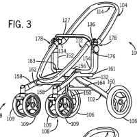
"[0137] Referring to FIG. 3, the PES System operational flow is shown by means of a flowchart. The PES System goes through an initialization procedure at 74. Then at each production step of the manufacturing production line 32 (FIG. 2) the MS Unit conducts appropriate measurements of the workpiece, which can be a photovoltaic cell, wafer, or module (sometimes called a WIP unit) at 76. MS Unit then sends measurement results to the PMC System at 78. The PMC System receives and processes the data at 80. Based on that information, the PMC System can either or both send feed forward or feedback recipe instructions to process tools at 82 and/or send handling instructions to the relevant MS Unit at 84. The appropriate MS Unit then either advances, discards or buffers the workpiece at 86."
図3を参照すると、上記PESシステムの動作フローがフローチャートにより示される。該PESシステムは、74にて初期化処理を経由する。その後、76にて、製造生産ライン32(図2)の各生産工程において、各MSユニットは、(一定の場合にはWIP単位体と称される)光起電力電池、ウェハ、もしくは、モジュールであり得る被加工材の適切な測定を行う。MSユニットは次に、78にて、測定結果を上記PMCシステムへと送信する。80にて、該PMCシステムはデータを受信して処理する。その情報に基づいてPMCシステムは、82にてフィードフォワードもしくはフィードバック処理手順命令をプロセス・ツールに対して送信する、および/または、84にて取扱い命令を適切なMSユニットに対して送信する、のいずれか又は両方を行い得る。次に適切なMSユニットは、86にて、被加工材を進行させ、廃棄し、または、バッファリングする。
US2017363952(JP)
"[0149] Such a phase shift mask blank is configured to have a light-semitransmissive film (thin film for pattern formation) on a substrate, and the light-semitransmissive film is patterned to provide a shifter portion, so that a halftone type phase shift mask is manufactured. In order to prevent pattern defects of the transfer target substrate due to a light-semitransmissive film pattern formed on a transfer region based on light transmitted through the light-semitransmissive film, such a phase shift mask may have the light-semitransmissive film on the substrate and a light shielding film (light shielding band) thereon. In addition to the halftone type phase shift mask blank, there are mask blanks for a Levenson phase shift mask which is a substrate dug-down type where a substrate is dug by etching, etc. to provide a shifter portion, for an enhancer-type phase shift mask, and for a chromeless phase lithography (CPL) mask."
[0093] (2)ケイ素と窒素を含む材料、又は遷移金属及びケイ素(遷移金属シリサイド、特にモリブデンシリサイドを含む)の化合物を含む材料からなる光半透過膜を備えた位相シフトマスクブランク
かかる位相シフトマスクブランクとしては、基板上に光半透過膜(パターン形成用の薄膜)を有する形態のものであって、該光半透過膜をパターニングしてシフタ部を設けるタイプであるハーフトーン型位相シフトマスクが作製される。かかる位相シフトマスクにおいては、光半透過膜を透過した光に基づき転写領域に形成される光半透過膜パターンによる被転写基板のパターン不良を防止するために、基板上に光半透過膜とその上の遮光膜(遮光帯)とを有する形態とするものが挙げられる。また、ハーフトーン型位相シフトマスクブランクのほかに、基板をエッチング等により掘り込んでシフタ部を設ける基板掘り込みタイプであるレベンソン型位相シフトマスク用、エンハンサー型位相シフトマスク用、及びCPL(Chromeless Phase Lithography)マスク用の各マスクブランクが挙げられる。
US2016167256(JP)
"[0003] In the imprint molds used in such nanoimprint technique, a fine uneven pattern (main pattern) for fabricating, for example, a wiring pattern in a semiconductor device is formed on a pattern formation surface. Then, a fine uneven pattern (dummy pattern, alignment mark, etc.) of a size larger than that of the main pattern is typically also formed on the pattern formation surface with the object of facilitating the release of the imprint mold and aligning the imprint mold with the transfer substrate such as a semiconductor substrate during the imprint processing. Along with the progress in the miniaturization of semiconductor devices produced by nanoimprinting using such imprint molds, the size of the main pattern in the imprint molds has been reduced to less than several tens of nanometers."
かかるナノインプリント技術にて用いられるインプリントモールドにおいては、半導体デバイスにおける配線パターン等を作製するための微細凹凸パターン(メインパターン)がパターン形成面に形成されている。そして、一般に、そのパターン形成面には、インプリントモールドの剥離容易性や、インプリント処理時におけるインプリントモールドと半導体基板等の被転写基板との位置合わせ等を目的とした、当該メインパターンよりも寸法の大きい微細凹凸パターン(ダミーパターン、アライメントマーク等)も形成されている。このインプリントモールドを用いたナノインプリントにより製造される半導体デバイスの微細化が進行するのに伴い、現在、インプリントモールドにおけるメインパターンの寸法も数十nm以下程度にまで微細化されてきている。
US2015214509(JP)
"[0004] Another example is a transfer method using a radiant ray of laser light for example, as disclosed in Patent Literature 1. Transfer method is a method of transferring a transfer layer to a transfer-target substrate for forming an EL light-emitting element. The transfer layer includes a light-emitting material and is formed on a transfer substrate. Specifically, first, a transfer substrate is formed, which includes a supporting member and a transfer layer formed thereon. Next, the transfer substrate is disposed to face the transfer-target substrate. Finally, the transfer substrate is irradiated with a radiant ray under a reduced pressure environment. Consequently, the transfer layer is transferred to the transfer-target substrate, and the light-emitting layers are formed on the transfer-target substrate."
[0004] また、特許文献1に示すように、レーザーなどの輻射線を用いた転写法がある。転写法は、転写基板に形成された、発光材料を含む転写層を、EL発光素子を形成するための被転写基板に転写する方法である。具体的には、まず、支持材に転写層が形成された転写基板が形成される。そして、この転写基板は、被転写基板に対向配置される。そして、減圧環境下で輻射線が転写基板に照射される。これにより、転写層が被転写基板に転写され、被転写基板上に発光層が形成される。
EP2848391(JP)
"[0003] Nanoimprinting techniques have been proposed as concavo-convex structure fabrication techniques whereby the problems described above can be overcome. Among the proposed techniques, an optical nanoimprinting has garnered attention from the perspectives of transfer accuracy and ease of use. In an optical nanoimprinting method, a mold on which a nanoscale concavo-convex structure is formed is pressed to a liquid resist layer formed on a surface of a transfer substrate, and the concavo-convex structure formed on the mold is thereby transferred to the surface of the transfer substrate."
[0003] これらの問題点を解消し得る凹凸構造加工技術として、ナノインプリント技術が提案されている。なかでも、転写精度及び容易性の観点から、光ナノインプリント法が注目を集めている。光ナノインプリント法においては、ナノスケールの凹凸構造が形成されたモールドを、被転写基板の表面に形成された液状のレジスト層に押圧することで、モールドに形成された凹凸構造を、被転写基板の表面に転写形成する。
substrate to be transferred onto
最新の画像[もっと見る]
-
 Are they exceptions?
1週間前
Are they exceptions?
1週間前
-
 Are they exceptions?
1週間前
Are they exceptions?
1週間前
-
 今年もスイカ!
4週間前
今年もスイカ!
4週間前
-
 今年もスイカ!
4週間前
今年もスイカ!
4週間前
-
 方向:冠詞
4週間前
方向:冠詞
4週間前
-
 方向:冠詞
4週間前
方向:冠詞
4週間前
-
 side by side
1ヶ月前
side by side
1ヶ月前
-
 side by side
1ヶ月前
side by side
1ヶ月前
-
 side by side
1ヶ月前
side by side
1ヶ月前
-
 side by side
1ヶ月前
side by side
1ヶ月前


※コメント投稿者のブログIDはブログ作成者のみに通知されます