


US2005255253
25. An apparatus for curing ink, comprising:
a chamber having:
an electron beam emitter adapted to emit an electron beam;
an electron beam emitter positioning device, wherein the electron beam emitter positioning device is adapted to support the electron beam emitter at a distance above a surface of a substrate containing ink and move the electron beam emitter so as to scan an electron beam over the surface of the substrate and cure ink present on the substrate.
an ozone detector adapted to detect a level of ozone in the ink curing chamber;
a controller coupled to the ozone detector and adapted to receive a signal from the ozone detector, determine if the level of ozone is above a predetermined level, and if so activate at least one of purging the ink curing chamber and turning off the electron beam;
an x-ray detector coupled to the controller and adapted to detect a level of x-ray leakage from the ink curing chamber, wherein the controller is adapted to receive a signal from the x-ray detector, determine if the level of x-ray leakage is above a predetermined level, and if so initiate turning off the electron beam;
an interlock system coupled to the controller and adapted to detect an open or unlocked condition of a door of the ink curing chamber, wherein the controller is adapted to receive a signal indicating whether the door of the ink curing chamber is open or unlocked and, if so, initiate turning off the electron beam; and
a purging system coupled to the controller and adapted to purge the ink curing chamber with an inert gas in response to an activation signal from the controller,
wherein the electron beam emitter positioning device is adapted to remain at a constant z-axis position during substrate load/unload operations,
wherein the apparatus further includes a stage adapted to support the substrate, and
wherein the stage is adapted to be lowered so as to allow stationary lift pins to protrude through the stage, support the substrate, and provide clearance above and below the substrate when the stage is lowered.
【請求項25】
電子ビームを送出する電子ビーム送出器と、
電子ビーム送出器の位置決め装置と
を有し、
前記電子ビーム送出器の位置決め装置はインクの載った基板の表面上の所定の距離のところで前記電子ビーム送出器を支持し、前記基板の前記表面にかけて電子ビームを走査し、前記基板上にあるインクをキュアするように、前記電子ビーム送出器を動かし、
前記インク・キュアリング・チャンバ内のオゾンのレベルを検出するオゾン検出器と、
前記オゾン検出器に接続され、前記オゾン検出器からの信号を受信し、前記オゾンのレベルが所定のレベルより大きいかどうかを決定し、もしそうであれば、前記インク・キュアリング・チャンバをパージするか、前記電子ビームをオフ状態にするかの少なくともいずれか1つを起動するコントローラと、
前記コントローラに接続され、前記インク・キュアリング・チャンバからのX線漏れのレベルを検出し、前記コントローラは前記X線検出器からの信号を受信し、前記X線の漏れのレベルが所定のレベルより大きいかどうかを決定し、もし大きければ前記電子ビームをオフ状態にするX線検出器と、
前記コントローラに接続され、前記インク・キュアリング・チャンバのドアの開閉若しくはアンロック状態を検出し、前記コントローラは前記インク・キュアリング・チャンバの前記ドアが開いているか又はアンロック状態であるかどうかを示す信号を受信し、もしそうであれば前記電子ビームをオフ状態とするインターロック・システムと、
前記コントローラに接続され、前記コントローラからの起動信号に応じて、不活性ガスにより前記インク・キュアリング・チャンバをパージするパージング・システムと、
を備え、
前記電子ビーム送出器の位置決め装置は基板の搬入・搬出動作の間、固定のZ軸の位置に止まり、
前記装置は更に前記基板を支持するステージを含み、
前記ステージは前記ステージを介して固定のリフトピンが突出することを許容し、前記基板を支持し、前記ステージが降下するときに前記基板の上及び下のクリアランスをもたらすように低くなる
インクをキュアリングするための装置。
US10358715
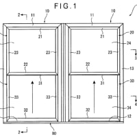
The chamber body 302 may be manufactured from a material suitable to withstand temperatures of up to about 300° C. For example, the chamber body 302 may be formed from aluminum, alloys thereof, stainless steel, and other suitable metallic materials. A slit valve opening 360 is formed in the chamber body 302 to allow for ingress and egress of a substrate to and from the process volume 310. A slit valve door 358 is coupled to the chamber body 302 and may be moveable to seal and unseal the slit valve opening 360. In one embodiment, the slit valve door 358 is formed from the same materials as the chamber body 302. Alternatively, the slit valve door 358 may be formed from materials different form the chamber body 302.
チャンバ本体302は、約300°Cまでの温度に耐える適切な材料から製造されていてよい。例えば、チャンバ本体302は、アルミニウム、その合金、ステンレス鋼、及び他の適切な金属材料から形成されていてよい。チャンバ本体302内にスリットバルブ開口部360が形成され、処理空間310との間の基板の搬入と搬出を可能にする。スリットバルブドア358が、チャンバ本体302に連結されており、スリットバルブ開口部360を封止及び開封するために可動であってよい。一実施形態では、スリットバルブドア358は、チャンバ本体302と同じ材料から形成されている。代わりに、スリットバルブドア358は、チャンバ本体302とは異なる形態の材料から形成されていてもよい。
US10431480
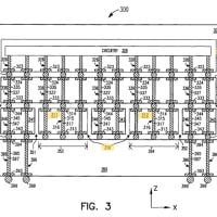
Continuing to refer to FIG. 1, the processing chambers 108, the rotation module 106, the transfer chambers 104a, 104b, and the load lock chamber 110 are connected to form a vacuum tight platform 116. One or more pump systems 118 are coupled to the load lock chamber 110, the transfer chambers 104a, 104b, the rotation module 106, and the processing chambers 108. In FIG. 1, a single pump system 118 is shown coupled to the load lock chamber 110 to avoid drawing clutter. The pump system 118 controls the pressure within the processing system 100. The pump system 118 may be utilized to pump down and vent the load lock chamber 110 as needed to facilitate entry and removal of substrates from the vacuum tight platform 116.
[0022] 図1の参照を続けると、処理チャンバ108、回転モジュール106、移送チャンバ104a、104b、及びロードロックチャンバ110が接続されて、真空気密プラットフォーム116を形成する。1つ以上のポンプシステム118が、ロードロックチャンバ110、移送チャンバ104a、104b、回転モジュール106、及び処理チャンバ108に連結される。図1において、図面が乱雑になるのを回避するため、1つのポンプシステム118だけが、ロードロックチャンバ110に連結されているのが示される。ポンプシステム118は、処理システム100内の圧力を制御する。ポンプシステム118は、真空気密プラットフォーム116への基板の搬入及び搬出を容易にするため、必要に応じて、ロードロックチャンバ110をポンプダウンし通気するために利用され得る。
WO2013120054
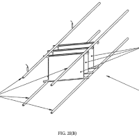
[120] The processing apparatus described herein may also be configured to allow entry/exit of substrates to/from the processing apparatus in more than one location in the processing apparatus. For example, referring to Fig. 23A, an EFEM 2060A, 2060B may be connected to both ends of the transport tunnel formed by the vacuum modules 2040A, 2040B, 2040C, the vacuum tunnel 2010 and the automation modules 2030A, 2030B. Here, in one aspect, substrates may enter the processing apparatus through EFEM 2060A and exit through EFEM 2060B or vice versa. In other aspects the substrates may enter and exit through any one or more of EFEM 2060A and 2060B. Referring also to Fig. 23B an entry/exit point for adding/removing substrates to/from the processing apparatus may also be located between the ends of the transport tunnel. For example, vacuum modules, such as vacuum module 2040', may be added to the transport tunnel to allow connection of an EFEM 2060C at a midpoint, or at any other point between the ends of the transport tunnel. Here, in one aspect, substrates may enter the processing apparatus through EFEM 2060A and exit through EFEM 2060B and/or EFEM 2060C; enter the processing apparatus through EFEM 2060B and exit through EFEM 2060A and/or EFEM 2060C; enter the processing apparatus through EFEM 2060C and exit through EFEM 2060A and/or EFEM 2060B. In other aspects the substrates may enter or exit through any one or more of EFEM 2060A, 2060B and 2060C to form any suitable process flow through the processing apparatus .
本明細書に記載される処理装置は、処理装置の2つ以上の場所での、処理装置への/処理装置からの基板の搬入/搬出を可能にするように構成されてもよい。例えば、図23Aを参照すると、EFEM2060A、2060Bは、真空モジュール2040A、2040B、2040C、真空トンネル2010および自動化モジュール2030A、2030Bによって形成される搬送トンネルの両端に接続され得る。ここで、一態様において、基板は、EFEM2060Aを通して処理装置に入り、EFEM2060Bを通して処理装置を出てもよく、逆の場合も同様である。別の態様において、基板は、EFEM2060A、EFEM2060Bの任意の1つまたは2つ以上を通して出入りし得る。また、図23Bを参照すると、処理装置から/処理装置へ、基板を、追加/除去するための搬入/搬出点も、搬送トンネルの端部間に位置付けられ得る。例えば、真空モジュール2040’などの真空モジュールは、搬送トンネルの中間点、または搬送トンネルの端部間の他の任意の点でのEFEM2060Cの接続を可能にするために、搬送トンネルに加えられ得る。ここで、一態様において、基板は、EFEM2060Aを通して処理装置に入り、EFEM2060Bおよび/またはEFEM2060Cを通して出てもよいし、EFEM2060Bを通して処理装置に入り、EFEM2060Aおよび/またはEFEM2060Cを通して出てもよいし、EFEM2060Cを通して処理装置に入り、EFEM2060Aおよび/またはEFEM2060Bを通して出てもよい。別の態様において、基板は、EFEM2060A、2060B、2060Cの任意の1つまたは2つ以上を通して出入りしてもよく、処理装置を通る任意の適切なプロセスの流れを形成する。
US7806383
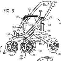
Substrates are typically transferred into and out of the process chamber 104 as the substrate moves through a desired fabrication sequence. For example, a transfer chamber 102 may be coupled to the process chamber 104 to facilitate placing a substrate on, or removing the substrate from, the substrate support 118. An opening 106 is disposed in respective adjacent walls of the transfer chamber 102 and the process chamber 104 to facilitate transfer of a substrate into and out of the process chamber 104. A valve assembly 108 is disposed proximate the opening 106 to facilitate selectively sealing the opening 106.
基板は所要の製造シーケンスに従い進むにつれ、典型的にはプロセスチャンバ104へと搬送され、又、そこから搬出される。例えば、搬送チャンバ102は、基板支持体118上に基板を載置するために、若しくは、そこから基板を取り除くために、プロセスチャンバ104に結合される。開口106はプロセスチャンバ100への基板の搬入、及び、そこからの基板の搬出を行うために、搬送チャンバ102及びプロセスチャンバ104のそれぞれ近傍の壁に設けられる。バルブアセンブリ108は開口106の選択的に密閉状態にするために、開口106の近傍に設けられる。


※コメント投稿者のブログIDはブログ作成者のみに通知されます