


EP3760519(JP)
[0030] Note that in the hat-shaped member 12 of this embodiment, because the top sheet portion 12a and the vertical wall portions 12b are connected with each other by curved surfaces,
【0030】
なお、本実施形態のハット状部材12においては、天板部12aと縦壁部12bとがそれぞれ曲面で接続されていることから、
the end portions in the width direction W of the top sheet portion 12a include the curved surfaces, and the "plane portion" of a member including the plane and the curved surfaces in this description may mean boundary portions between the plane and the curved surfaces, namely, a portion from an R end of one curved surface to an R end of the other curved surface.
天板部12aの幅方向Wの端部には曲面が含まれることになるが、本明細書における平面と曲面を含む部材の“平面部”とは、平面と曲面の境界部分、すなわち一方の曲面のR止まりから他方の曲面のR止まりまでの部分を指しても良い。
According to this definition, the plane portions P of the vertical wall portions 12b of the hat-shaped member 12 are each set to be a portion from the R end of the curved surface on the top sheet portion 12a side to the R end of the curved surface on the flange portion 12c side.
この定義によれば、ハット状部材12の縦壁部12bの平面部Pとは、天板部12a側の曲面のR止まりからフランジ部12c側の曲面のR止まりまでの部分となる。
Further, as a more detailed definition of the "plane portion", when a sheet thickness of the member (the top sheet portion 12a, the vertical wall portions 12b, or the like) is set as t, and a curvature radius is set as r, r/t ≥ 10000 may be defined as the plane portion P.
また、“平面部”のより詳細な定義としては、部材(天板部12a、縦壁部12b等)の板厚をt、曲率半径をrとした場合に、r/t≧10000を平面部Pと規定しても良い。
Since the surface of the flat sheet 11 is also naturally the plane portion P, all of the FRP members 20 used in this embodiment are provided on the inner surfaces of the plane portions P of the hollow member 10. Note that as indicated in a later-described example, the hollow member 10 need not have a curved surface portion, and may be formed by only the plane portion.
平板11の表面も当然に平面部Pであることから、本実施形態で用いられているFRP部材20は、全て中空部材10の平面部Pの内面に設けられていることになる。なお、後述する例で示すように、中空部材10は、曲面部を有さず、平面部のみで構成されていてもよい。
US100766444(JP)
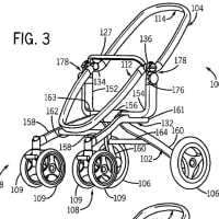
A curved portion (or round portion) 5 is provided along the border between each of the two walls 1b and the top plate 1a. That is, an end portion of the wall 1b including the one end thereof is round and curved in shape. As such, the surface of the associated shoulder of the hat member, located along the border between the wall 1b and top plate 1a, is curved.
【0047】
2つの縦壁1bのそれぞれと天板1aとの境界部分には、湾曲部(R)5が形成されている。すなわち、縦壁1bの一方端を含む端部は、丸く湾曲した形状となっている。これにより、縦壁1bと天板1aとの境界におけるハット部材の肩部の表面は、曲面になる。
The height H of the wall 1b as measured in the direction perpendicular to the closing plate 2 is determined assuming that the curved (or round) portion 5 is part of the wall 1b. That is, that border of the curved (or round) portion 5 which is adjacent to the top plate 1a (or end of the round portion), 5b, defines one end of the wall 1b. The associated first ridge 1ab is adjacent to the one end of the wall 1b, i.e. the border of the round portion 5b.
この湾曲部(R)5は、縦壁1bの一部であるとして、縦壁1bの、クロージングプレート2に垂直な方向における高さHが決定される。すなわち、湾曲部(R)5の天板1a側の端のR境界(R止まり)5bを、縦壁1bの一方端とする。第1の稜線1abは、縦壁1bの一方端すなわちR境界5bに隣接する。
[0032] FIG. 7 is a graph showing the relationship between the lifter pad force and the average thickness of the circumferential wall of the body in the first compression drawing process, using the common cold-rolled steel sheet having a thickness of 1.8 mm as the base metal sheet. In FIG. 7 , the vertical axis represents an average thickness of the circumferential wall of the body after the first compression drawing process, and the horizontal axis represents a first compression drawing lifter pad force (kN).
【0029】
図7は、素材金属板として、板厚1.8mmの普通鋼冷延鋼板を用い、第1圧縮絞り工程におけるリフターパッド力と胴部周壁平均板厚との関係を示すグラフである。図7では、第1圧縮絞り後の胴部周壁平均板厚を縦軸とし、第1圧縮絞りリフターパッド力(kN)を横軸としている。
It should be noted that the average thickness of the circumferential wall of the body is obtained by averaging the thickness of the circumferential wall from a R stop on the flange side of the shoulder portion of the punch 41 to a R stop on the top wall side of the shoulder portion of the die 40.
なお、胴部周壁平均板厚とは、パンチ41の肩部のフランジ側のR止まりからダイ40の肩部の頂壁側のR止まりまでの周壁の板厚を平均化したものである。
It can be seen that the average thickness of the circumferential wall of the body increases almost linearly as the first compression lifter pad force increases. It can be also seen that a first compression lifter pad force of about 15 kN or more increases the thickness as compared with the average thickness of the circumferential wall of the body in the preliminary drawing.
胴部周壁平均板厚は、第1圧縮リフターパッド力が高くなるにつれてほぼ直線的に増加していることが分かる。また、第1圧縮リフターパッド力をおよそ15kN以上にすることで、予備絞りの胴部周壁平均板厚より増肉することが分かる。
US2020102026(JP)
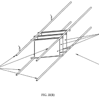
[0042] The discharge port 42 of the duct 40 has a vertically elongate shape and is in front of the wheel house 5. The traveling air is discharged from the discharge port 42 to a vertically elongate region on the front portion 6a of the front wheel 6. The discharge port 42 ate duct 40 is formed so that the traveling air passing through the duct 40 collides against an edge 6c (R-end) between the front portion 6a and a flank 6b of the front wheel 6 facing the outside of the vehicle. For example, the discharge port 42 has a shape laterally centered on the edge 6c of the front wheel 6 and having a 5 mm width from the center in both sides.
0044】
また、前記ダクト部40の排出口42は、前記ホイルハウス5の前端において、上下方向に長い扁平な形状とされ、前記前輪6の前部6aの上下方向に長い領域に走行風を排出するように形成されている。また、前記ダクト部40の排出口42は、前記ダクト部40を通過した走行風が、前記前輪6の前部6aと車外側の側部6bとの間の角部6c(R止まり)に当たるように形成され、例えば、前記前輪6の角部6cを中心として、車体幅方向において左右それぞれ5mmの幅を持った通路で形成されている。


※コメント投稿者のブログIDはブログ作成者のみに通知されます