EP4337565(WESTROCK PACKAGING SYSTEMS LLC [US])
Figure 4 is a plan view from above of a blank for forming an article carrier according to a third embodiment;
【図4】第3の実施形態による物品キャリアを形成するためのブランクを上から見た平面図である。
US11839851(SHELL USA INC [US])
[0021] FIG. 7 is a bottom up plan view of a portion of the lateral flow reactor with the plane and direction of sight shown by section line 7 - 7 in FIG. 6 , in accordance with an embodiment of the present disclosure;
【図7】本開示の実施形態による、図6の切断線7-7によって示される平面及び視線方向で、横方向流反応器の一部を下から見た平面図である。
US2022314649(XEROX CORP [US])
[0012] FIG. 4 is a plan view from above the printhead assemblies of one embodiment of an inkjet printing system including an air flow control system.
【図4】気流制御システムを含むインクジェット印刷システムの一実施形態の印刷ヘッドアセンブリの上から見た平面図である。
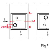
US11561567(PENN ENG & MFG CORP [US])
[0013] FIG. 1 is a top front perspective view.
【図1】図1は上部正面から見た斜視図である。
[0014] FIG. 2 is a top left perspective view.
【図2】図2は上部左側から見た斜視図である。
[0015] FIG. 3 is a front sectional elevation view.
【図3】図3は正面断面立面図である。
[0016] FIG. 4 is a bottom plan view.
【図4】図4は底面平面図である。
[0017] FIG. 5 is a front elevation partial sectional view taken from FIG. 4 as indicated.
【図5】図5は図4の正面から見た部分横立面図である。
[0018] FIG. 6 is a top plan sectional view taken from FIG. 5 as indicated.
【図6】図6は図5の上からみた平面断面図である。
[0019] FIG. 7 is a bottom plan sectional view taken from FIG. 5 as indicated.
【図7】図7は図5の底から見た平面断面図である。
[0020] FIG. 8 is a front elevation sectional view showing the extended position.
【図8】図8は前進位置を示す正面立面断面図である。
[0021] FIG. 9 is a front elevation sectional view showing the retracted position.
【図9】図9は後退位置を示す正面立面断面図である。
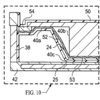
[0022] FIG. 10 is a front elevation sectional view of a second embodiment.
【図10】図10は第2実施態様を示す正面断面の立面図である。
[0023] FIG. 11 is a bottom plan view.
【図11】図11は底から見た平面図である。
[0024] FIG. 12 is a top plan view of the cam ring component of the second embodiment.
【図12】図12は第2実施態様のカムリング構成部材を上から見た平面図である。
[0025] FIG. 13 is a section view taken from FIG. 12 as shown in that figure.
【図13】図13は図12の断面図である。
[0026] FIG. 14 is an elevation sectional view showing the assembled push button device of the second embodiment.
【図14】図14は第2実施態様に係る組立状態のプッシュボタン装置を示す立面断面図である。
US11940152(GEN ELECTRIC [US])
[0073] FIGS. 9 - 12 illustrate plan views of a fuel injector 200 , as viewed from radially outward of the fuel injector 200 along the radial direction R, in accordance with embodiments of the present disclosure.
【0061】
図9~図12が、本開示の実施形態による燃料インジェクタ200について、半径方向Rに沿って燃料インジェクタ200の半径方向外側から見た平面図を示している。
US10124219(TAYLOR MADE GOLF CO [US])
[0160] FIG. 89 is a bottom plan view of a raised platform of the sole port of FIG. 85A.
【図89】図85Aのソールポートの隆起したプラットホームの下から見た平面図である。