「一端」に対する「他端」は初出ではanother endとした方が良いのでしょうか?クレームではその方が良さそうな気がしますが、詳細な説明では?
ネイティブ例ではパイプ等、一端と他端が明らかと思える場合、初出でもone end, the other endとしている例が多いように感じたかと思えば、やはりone end, another endとしている場合もあります。
US2020268311
[0037] According to the illustrated embodiment, the controller 124 analyzes the DC signal from the light sensor 122
【0026】
図示の実施形態によれば、ブロック210で、コントローラー124は、光センサー122からのDC信号を分析して、
to determine if there is a decrease in the signal between one end of the light sensor 122 and the other(*初出で定冠詞)(e.g., between one end of a linear array of individual light sensing elements and the other) at block 210 .
光センサー122の一端と他端との間(例えば、個々の光検出素子の線形配列の一端と他端の間)で信号の減少があるかどうかを判定する。
US10112749
[0034] The closure strip is juxtaposed between the disc shaped cap and the container head.
【0023】
蓋用細片は、ディスク状キャップと容器頭部との間に並べられている。
The closure strip is preferably an elongate rectangular strip having a preferred rectangular cross section.
蓋用細片は、好ましくは断面が長方形の細長い長方形の細片であることが好ましい。
The closure strip comprises on its upper surface a longitudinal recess slidably engagable with the arcuate monorail provided on the bottom surface of the disc shaped cap.
蓋用細片は、その上面に、ディスク状キャップの底面に設けられた弓状の単一レールと摺動係合可能な長手方向の凹部を有する。
The closure strip comprises on its lower surface at a distal end with a pair of legs which are slidably engagable with the pair of parallel recesses provided on the container head.
蓋用細片は、その下面の遠位端において、容器頭部に設けられた1対の平行な凹部と摺動係合可能な1対の脚部を備える。
At the other longitudinal proximal end of the closure strip, on the bottom surface is provided a plug capable of closing the outlet port provided on the container head.
蓋用細片の長手方向の近位の他端に、容器頭部に設けられた出口ポートを閉じることができるプラグが、底面に設けられている。
The closure strip is provided on its side edges with a pair of ears capable of sliding from one end of the rectangular cutouts of second pair of railings to the other end(*初出で定冠詞).
蓋用細片は、その側縁部に、第2対目のレールにおける長方形の切り込みの一端から他端にまで摺動することができる1対の耳を備える。
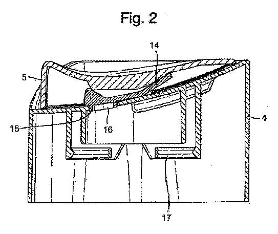
[0043] Referring to FIG. 2, the closure strip ( 14 ) is juxtaposed between the disc shaped cap ( 5 ) and the container head ( 4 ).
【0032】
図2を参照すると、蓋用細片(14)が、ディスク状キャップ(5)と容器頭部(4)との間に並べられている。蓋用細片が閉位置にある様子が示されている。

The closure strip is shown in the closed position where the plug ( 15 ) sits flush into the outlet port ( 16 ) thereby closing the outlet of the container, thus providing leak-proof closure.
閉位置では、プラグ(15)が出口ポート(16)内に同じ高さになるように配置されており、これにより容器の出口が閉じられ、したがって中身が漏れることなく容器が閉じられる。
The container head ( 4 ) is provided on the bottom of the top surface with means for snap-fitting ( 17 ) the container head on to the container (not shown).
容器頭部(4)は、上面の底部に、容器頭部を容器(不図示)にスナップフィットさせるための手段(17)を備える。
[0050] When in use, to open the container, the raised portion ( 13 ) is pushed back in the horizontal direction with a thumb or a finger.
【0039】
使用する際は、容器を開けるために、親指又はそれ以外の指で水平方向後ろに隆起部(13)を押す。
The disc shaped cap ( 5 ) slides back on the top surface ( 7 ) due to the sliding engagement of the parallel tracks ( 11 ) with the first pair of parallel railings ( 19 ).
ディスク状キャップ(5)は、平行軌道(11)と第1対目の平行レール(19)とが摺動係合しているため、上面(7)上を後ろに摺動する。
Simultaneously, the centrally aligned monorail ( 22 ) with the arcuate profile causes the closure strip ( 14 ) to horizontally slide backwards in the longitudinal recess ( 23 ) and pivot vertically with the plug ( 15 ) coming unplugged from the outlet port ( 16 ).
同時に、中央に並べられた弓状の断面を有する単一レール(22)により、蓋用細片(14)が、長手方向の凹部(23)において後方に水平に摺動し、出口ポート(16)から抜かれたプラグ(15)と共に垂直に旋回する。
The closure strip thus moves backwards with the pair of legs ( 24 ) sliding though the pair of parallel recesses ( 18 ) provided on the top surface of the container head ( 7 )
したがって蓋用細片は、1対の脚部(24)が容器頭部(7)の上面に設けられた1対の平行な凹部(18)を摺動する状態で後方に移動する。
and this horizontal movement is limited due to the pair of ears ( 25 ) restrained in movement between one end of the rectangular cutout ( 21 ) to the other.
この水平移動は、1対の耳(25)の動きが、長方形の切り込み(21)の一端と他端との間に制限されているため限定される。


To close the container, the disc shaped cap is pulled back in the horizontal direction
容器を閉じるためには、ディスク状キャップを水平方向に引き戻す。
to enable the disc shaped cap and concomitantly the closure strip to move back in the reverse path
この動作によりディスク状キャップと付随する蓋用細片とを、通路を引き返させて戻すことができる。
to cause the plug to sit flush in the outlet port to provide the necessary leak proof closing action.
これによりプラグが出口ポート内で同じ高さに位置するようになり、中身を漏らすことなく容器を閉じるという必要とされている動作を行うことができる。
US10112749
A metal shield 415 is shown as extending across the package from one end of the memory die to the other end(*他端;初出で定冠詞)of the memory die and across the application processor. This metal shield serves to isolate noise from the digital circuits of the memory application processor and power management unit from other components in the package.
US8727208
In one embodiment of the invention, the mechanical device adapted to roll the pill could be a tube at an incline through which the pill would tumble and roll as it proceeds from one end of the tube to the other end(*他端;初出で定冠詞). Also, the tube could have protrusions such as those in a clothes washer to promote tumbling and rolling of the pill. The pill could exit the tube and freely fall through air or through some other transparent medium such as water or oil. Furthermore, there could be one or more optical devices recording images of the pill as it traversed through the tube and then fell through air or the transparent medium.
US10679782
In some embodiments, ISOC layer 501 is coupled to another end(*他端;初出)of FM2 203 while SOC layer 204 is coupled to one end of FM2 203. In some embodiments, ISOC layer 501 is formed of the same material as ISOC layer 201. In some embodiments, ISOC layer 501 is coupled to ground. In some embodiments, non-magnetic conductor 505 b is coupled to ISOC layer 501. In some embodiments, non-magnetic conductor 505 b is parallel to non-magnetic conductor 205. In some embodiments, non-magnetic conductor 505 b is formed of Cu. In other embodiments, other types of non-magnetic conductors may be used. For example, Al may be used instead of Cu. In some embodiments, transistor MN2 is coupled to FM2 203 such that it its source terminal is coupled closer to the end of ISOC layer 501 than to the other end(*既出なので定冠詞)of FM2 203 which is coupled to SOC layer 204. In some embodiments, transistor MN2 is controlled by another clocking voltage V′cl (e.g., periodic input voltage which is an inverse of clocking voltage Vcl).


※コメント投稿者のブログIDはブログ作成者のみに通知されます