


US10293131
"With reference to FIG. 5, the illustrated sealing flange 208 comprises an extended surface 210, at least a portion of which will abut a skin surface of a face of a patient P. The extended surface 210, which has one end portion that is connected to the perimetric edge 206, defines a pocket-like structure that captures air or pressure from the air supply and that urges the flange 208 of the interface body 200 toward the face of the patient P to a desired degree. The sealing flange 208 can define at least a part of a sealing portion 212 of the illustrated seal member 202. The sealing portion 212 faces the patient, or is closest to the patient, in use. With reference to FIG. 6, the sealing portion 212 of the illustrated seal member 202 can be connected to an enclosing portion 214 of the seal member 202 at the perimetric edge 206, which can be defined by the rolled edge or by a radiused edge. "
図5を参照すると、図の密着フランジ208は延長面210を含み、その少なくとも一部が患者Pの顔の皮膚表面と接触することになる。延長面210は、その一方の端部が周辺縁206に接続されて、ポケット状の構造を画定し、これが空気供給手段からの空気と圧力を捕捉して、インタフェース本体200のフランジ208を患者Pの顔面に向かって所望の程度まで付勢する。密着フランジ208は、図のシール部材202の密着部212の少なくとも一部を画定できる。密着部212は使用時に患者に面し、または患者に最も近くなる。図6を参照すると、図のシール部材202の密着部212は、湾曲した縁辺またはアールの付いた縁辺により画定可能な周辺縁206においてシール部材202の包囲部214に接続できる。
WO2016141097
"In the context of the characterization of a "curved" wave pattern of corrugations, in certain instances the corrugation pattern is not the result of a folded or creased shape provided to the media, but rather the apex 7a of each ridge and the bottom 7b of each trough is formed along a radiused curve. A typical radius for such z-filter media would be at least 0.25 mm and typically would be not more than 3 mm."
波型の「湾曲」波パターンの特徴に関して、特定の例では、波形パターンは濾材に付けられた折畳み、または折り目形状の結果ではなく、各畝の頂点7aと各谷の底部7bがアールの付いた曲線に沿って形成される。このようなZ型濾材の典型的な半径は、少なくとも0.25mmであり、典型的に3mm以下である。
WO2006110227
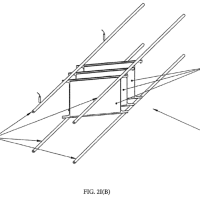
"[0043] The rear swing arm bearing 107 (Fig. 5) includes the protrusion 61 that rides within the keyhole-shaped slot 60. The protrusion 61 (Fig. 8) includes opposing flat side surfaces 130 and 131 defining a dimension about equal to a width of the long portion 110 of the slot 60. By this arrangement, the protrusion 61 is adapted to slide along the long portion 110 (see Fig. 7). The protrusion 61 (Fig. 8) also includes radiused end surfaces 132 and 133 shaped to rotatingly engage the circular portion 134 of the slot 60. (See Fig. 9.) As will be understood by those skilled in the art, this provides an advantageous arrangement since the armrest cap 57 can be adjusted horizontally in a fore/aft direction (i.e., a longitudinal direction) (compare Figs. 7-8) or can be adjusted horizontally translationally/laterally (compare Figs. 8-9). Also, it is clear from the Fig. 9 (and Fig. 5) that the armrest cap 57 can be adjusted horizontally rotationally /laterally by rotating one of the swing arms 58 and 59 more than the other swing arm 58 and 59."
スイングアーム上部軸受107(図5)は、鍵穴形のスロット60内に入る造形突出部61を含んでいる。造形突出部61(図8)は、スロット60の長い部分110の幅とほぼ等しい寸法を画定する対向する平坦な側面130及び131を含んでいる。この構成により、造形突出部61は、長い部分110に沿って摺動するようになっている(図7を参照)。造形突出部61(図8)は、スロット60の円形部分134と回転するように係合する形状になっているアールの付いた端面132及び133も含んでいる(図9を参照)。当業者には理解されるように、肘掛け蓋57は、前/後方向(すなわち縦方向)に水平に調節することができる(図7及び図8を比較)か、又は平行移動方向/横方向に水平に調節することができる(図8及び図9を比較)ため、これにより有利な構成が得られる。また、肘掛け蓋57は、スイングアーム58及び59の一方を他方よりも回転させることによって、回転方向/横方向に水平に調節できることが、図9(及び図5)から明らかである。
WO2017142982
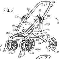
"[0008] The stop bracket portion may include an attachment area for connecting with the spacer portion. The attachment area may include one or more support posts for matingiy receiving the spacer portion by way of through openings (e.g., support post openings) in the spacer portion. The stop bracket portion may include a plurality of support posts. One or more of the support posts may include one or more features that create an interference fit with the spacer portion (e.g., one or more ribs, one or more shaped portions, one or more beads, or the like). The stop bracket portion may include a bracket attachment portion for matingiy engaging at least a portion of the column tube of the steering column assembly. The stop bracket portion may include a surface adapted to provide one or more Iines (e.g., two or mor parallel lines) of contact with the column tube to resist rocking when loaded in torsion (e.g., by radiused edges). "
ストップブラケット部分は、スペーサ部分と接続するための取り付け区域を含むことができる。取り付け区域は、スペーサ部分内の開口部(例えば、支持ポスト開口部)を通ることによってスペーサ部分を嵌合的に受け入れるための1又は2以上の支持ポストを含むことができる。ストップブラケット部分は、複数の支持ポストを含むことができる。1又は2以上の支持ポストは、スペーサ部分との締り嵌めを生成する1又は2以上の特徴部(例えば、1又は2以上のリブ、1又は2以上の成形部分、又は1又は2以上のビーズなど)を含むことができる。ストップブラケット部分は、ステアリングコラムアセンブリのコラムチューブの少なくとも一部分と嵌合的に係合するブラケット取り付け部分を含むことができる。ストップブラケット部分は、捩り荷重を受けた時に(例えば、Rの付いた縁部により)揺動に抵抗するためにコラムチューブと接触する1又は2以上の線(例えば、2又は3以上の平行線)を与えるようになった面を含むことができる。
US10213833
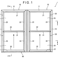
"Referring to FIGS. 1-9, and according to one embodiment, an enclosure 100 for fabricating a part 190 made from metal powder 180 or powdered metal is shown. The enclosure 100 includes a first sheet 110 and a second sheet 112. The first sheet 110 is coupled to the second sheet 112 to form the enclosure 100. Moreover, the first sheet 110 includes a first protrusion 114 and the second sheet 112 includes a second protrusion 116. Extending about a periphery 125 of the first protrusion 114 is a first flange 118. Similarly, extending about a periphery 127 of the second protrusion 116 is a second flange 120. In the illustrated embodiment, the first flange 118 extends about the entire periphery 125 of the first protrusion 114, and the second flange 120 extends about the entire periphery 127 of the second protrusion 116. In this manner, on a given plane or curved surface, the first and second flanges 118, 120 effectively surround the first and second protrusions 114, 116. The first protrusion 114 includes one or more sidewalls 122 and a fillet 124, and the second protrusion 116 includes one or more sidewalls 126 and a fillet 128. The fillets 124, 128 provide a radiused transition region between the sidewalls 122, 126, and the first and second flanges 118, 120, respectively. Although the first and second protrusions 114, 116 include fillets 124, 128 between the sidewalls 122, 126 and the first and second flanges 118, 120, in some implementations, the first and second protrusions 114, 116 do not include fillets such that the sidewalls transition directly into the first and second flanges without a radiused or otherwise gradual transition region. "
図1〜9を参照すると、及び一実施形態によると、金属粉末180または粉末化された金属から作られる部品190を作製するためのエンクロージャ100が示されている。エンクロージャ100には、第1のシート110及び第2のシート112が含まれる。第1のシート110は、第2のシート112に連結されてエンクロージャ100を形成している。さらに、第1のシート110には第1の隆起部114が含まれ、第2のシート112には第2の隆起部116が含まれている。第1の隆起部114の周縁125の周囲に延伸しているのは、第1のフランジ118である。同様に、第2の隆起部116の周縁127の周囲に延伸しているのは、第2のフランジ120である。示される実施形態では、第1のフランジ118は第1の隆起部114の周縁125全体の周囲に延伸し、第2のフランジ120は第2の隆起部116の周縁127全体の周囲に延伸している。こうして、所与の平面または曲面上で、第1及び第2のフランジ118、120は、第1及び第2の隆起部114、116を事実上取り囲んでいる。第1の隆起部114には1または複数の側壁122及びフィレット124が含まれ、第2の隆起部116には1または複数の側壁126及びフィレット128が含まれる。フィレット124、128によって、それぞれ、側壁122、126と第1及び第2のフランジ118、120との間の、Rが付いた移行領域が設けられている。第1及び第2の隆起部114、116には側壁122、126と第1及び第2のフランジ118、120との間にフィレット124、128が含まれているが、ある実施形態では、第1及び第2の隆起部114、116にはフィレットが含まれず、Rの付いたまたは他の緩やかな移行領域なしに、側壁が直接第1及び第2のフランジに移行している。
最新の画像[もっと見る]
-
 Are they exceptions?
20時間前
Are they exceptions?
20時間前
-
 Are they exceptions?
20時間前
Are they exceptions?
20時間前
-
 今年もスイカ!
2週間前
今年もスイカ!
2週間前
-
 今年もスイカ!
2週間前
今年もスイカ!
2週間前
-
 方向:冠詞
3週間前
方向:冠詞
3週間前
-
 方向:冠詞
3週間前
方向:冠詞
3週間前
-
 side by side
1ヶ月前
side by side
1ヶ月前
-
 side by side
1ヶ月前
side by side
1ヶ月前
-
 side by side
1ヶ月前
side by side
1ヶ月前
-
 side by side
1ヶ月前
side by side
1ヶ月前


※コメント投稿者のブログIDはブログ作成者のみに通知されます