goo blog サービス終了のお知らせ 

和英特許翻訳メモ

便利そうな表現、疑問、謎、その他メモ書き。思いつきで書いてます。
拾った用例は必ずしも典型例、模範例ではありません。

前方側に

2021-06-25 17:00:46 | 英語特許散策

US10317661
The U-shaped brackets mounted on the top of each assembly
各組立体の上に設置されるU形ブラケットは、

are optical home flag sensors configured to detect when the lifter head has reached the high end of its travel.
リフタヘッドがその行程の上側の端に到達したことを検出するように構成される光学式の家庭用フラグセンサである。

The vertical linear strip attached mid-plane to the front of the lifter on the left and to the rear of the lifter on the right
左側においてリフタの前方側に取り付けられかつ右側においてリフタの後方側に取り付けられるような形で平面の中央にある垂直方向線形ストリップが、

has a magnetic strip encoder to provide a signal corresponding to the lifter head distance from the home sensor in the vertical direction.
垂直方向における家庭用のセンサからのリフタヘッドの距離に対応する信号を提供するための磁気ストリップのエンコーダを有する。

EP3441300
[0035] In this illustrative example, each of skin splice angles 215 has a first tapered flange on its forward side.
【0035】
  この例示的な例では、外板スプライスアングル215はそれぞれ、外板スプライスアングル215の前方側に第1のテーパフランジを有する。

Each skin splice angle tapers from its center to the edge connecting it to the skin of the pressurized section of fuselage 202 .
各外板スプライスアングルは、外板スプライスアングルの中心から縁部にかけて細くなっていて、外板スプライスアングルを胴体202の与圧セクションの外板に連結している。

The taper on the forward flange is configured to provide a desired level of load transfer performance between parts and reduce or eliminate the need for shimming.
前方フランジのテーパは、部品相互間に所望の水準の荷重伝達性能を与え、シム入れの必要性をなくすように構成される。

WO2018111405
[0005] U.S. Patent No. 9,039,382, entitled "Blade Skirt" describes a turbine blade include details of the blade root.
【0005】
  「ブレードスカート」と題された米国特許第9,039,382号明細書は、ブレード根元の詳細を含むタービンブレードについて記載している。

The blade 300 typically has an airfoil 302, a platform 304, a shank 306, and a multi-lobe dovetail 308 having a fir tree configuration.
ブレード300は通常、翼形部302、プラットフォーム304、シャンク306、及びモミの木構造を有するマルチローブダブテール308を有する。

On the forward side of the blade 300, there is a forward angel wing 310.
ブレード300の前方側に、前方エンジェルウィング310がある。

On the aft side of the blade 300, there is a distal aft angel wing 312 radially inward of that is a proximal aft angel wing 314 with a gap therebetween.
ブレード300の後方側には、遠位後方エンジェルウィング312があり、その径方向内側には遠位後方エンジェルウィング312との間に間隙を有する近位後方エンジェルウィング314がある。

Proximal of the aft proximal angel wing 314, there is a fillet 316 that blends into a blade skirt 318.
後方近位エンジェルウィング314の近位には、ブレードスカート318に融合するフィレット316がある。

A recess may be provided within the shank portion 306 between the forward and aft sides of the blade 300.
ブレード300の前方側と後方側との間のシャンク部分306内に凹部を設けることができる。

Within that recess, there is a forward damper retention lug 324 and an aft damper retention lug 326, which are used in conjunction with one another to retain a damper (not shown).
その凹部内には、ダンパ(図示せず)を保持するために互いに関連して使用される前方ダンパ保持ラグ324及び後方ダンパ保持ラグ326がある。

The dovetail section 308 is inserted in a rotor (not shown) such that the dovetail lobes 328 mate with the rotor to radially fix the blade in place.
ダブテール部308は、ダブテールローブ328がロータと噛み合ってブレードを径方向に所定位置に固定するように、ロータ(図示せず)に挿入される。

コメント
  • X
  • Facebookでシェアする
  • はてなブックマークに追加する
  • LINEでシェアする

電圧が生じ

2021-06-25 15:43:53 | 英語特許散策

US2019339305
If the electrical current jumps to 100 mA, then R1 404 gives a volt,
もし電流が100mAへ急に変化(ジャンプ)すると、R404には、ある電圧が生じ

and the other two resistors R2 406 and R3 502 would be saturated, and the voltage across R1 404 can be used to determine the electrical current.
他の2つの抵抗器R406及びR502は飽和するであろうことから、電流を求めるのにR404にかかる電圧を利用できる。

This creates a logarithmic behavior for the circuit 500 and can create a more accurate electrical current measurement at all different magnitudes of electrical currents.
これは、回路500に対数関数的な動作(logarithmic behavior)を生成させ、あらゆる様々な大きさの電流において、より正確な電流測定値を生成できる。

In some embodiments, the resistance of the resistors in the circuit may be chosen in decade multiples, as illustrated above.
実施形態によっては、回路中の複数の抵抗器の抵抗値は、上述したように、10の倍数で選択されても良い。

US10219339
[0005] During operation, the current driver IC is enabled and sinks an output current from the supply node, through the LED, through the drive terminal, and onto a ground node.
【0005】
  動作中、電流ドライバICはイネーブルになり、供給ノードからの出力電流は、LEDを通り、駆動端子を通り、そして接地ノードにシンクする。

An output voltage is present between the cathode of the LED and the ground node.
LEDのカソードと接地ノードとの間に出力電圧が生じ

The output voltage typically varies due to charge and discharge cycles of the battery which cause the battery voltage to decrease over time.
出力電圧は通常、バッテリの充電及び放電サイクルによって変化し、これにより、時間の経過とともにバッテリ電圧が低下する。

The output voltage may also vary depending on the voltage and current demands across different applications.
出力電圧は、さまざまな用途での電圧と電流の要求に応じても変化する。

In addition, changes in temperature of the LED may also cause the output voltage to change.
さらに、LEDの温度の変化により、出力電圧が変化することもある。

EP3078040
 The addition of inductances L909 and L910 may create additional voltage transients on the supply voltage 902 and ground traces

as the load placed on supply voltage 902 changes due to current consumption changes by voltage regulator 901 or any other circuit that may be coupled to supply voltage 902, but not shown.
電圧レギュレータ901によるか又は電源電圧902に連結することができる任意の他の回路(図示せず)による電流消費の変動に起因して、電源電圧902にかかる負荷が変化するので、

インダクタンスL909及びL910を追加すると、電源電圧902及びグラウンドトレース上に、更なる過渡電圧が生じ可能性がある。

EP2648318
[0037] One significant advantage of the open-core flywheel architecture of the present disclosure is that rotor growth with speed significantly widens the speed range over which the power electronics can efficiently extract energy from the flywheel.
【0038】
  本開示のオープンコアフライホイールアーキテクチャの1つの著しい利点は、スピードに伴うロータの膨張により、パワーエレクトロニクスがフライホイールから十分にエネルギーを抽出することができるスピード範囲が著しく広がることである。

According to the open-core architecture of the present disclosure, the rotor's dimension grows radially as the flywheel speed increases.
本開示のオープンコアアーキテクチャによれば、ロータの寸法は、フライホイールスピードが増すにつれて半径方向に膨張する。

In addition, as the PMs of the M/G move farther away from the stator coils, the magnetic flux through the coil diminishes.
さらに、M/GのPMがステータコイルから遠ざかるにつれて、コイルを通る磁束が減少する。

This results in a voltage that is relatively constant over the upper speed range of the flywheel. 
これにより、フライホイールの上限スピード範囲にわたって比較的一定である電圧が生じ

WO20180160271
[0055] Considering the amplifier input of node 1016 does not short to ground,
【0043】
  [0055]ノード1016の増幅器入力がアースに短絡していないことを考えると、

the electrical pathway continues through the tissue resistance 1006 to a central node 1012,
電気経路は、組織の抵抗1006を通って中央ノード1012まで続き、

which has essentially the same voltage as the sensing node 1018 since there is little to no current through tissue resistance 1010 due to the large input impedance of the amplifier 1020 at node 1018.
中央ノード1012は、ノード1018での増幅器1020の大きな入力インピーダンスのために、組織の抵抗1010を通る電流がほとんどまたは全くないので、本質的に検知ノード1018と同じ電圧を持つ。

The electrical pathway continues from central node 1012 through additional tissue resistance 1008 to the stimulation node 1014 which is at system ground.
電気経路は、中央ノード1012からさらなる組織の抵抗1008を通ってシステムアースである刺激ノード1014まで続く。

Thus, this flow of current produced by the heart 1002 results in a first voltage on node 1016 while a second voltage occurs on the node 1018. 
従って、心臓1002によって生成されたこの電流の流れは、ノード1016に第1の電圧が生じ、一方、ノード1018に第2の電圧が生じるという結果をもたらす。

コメント
  • X
  • Facebookでシェアする
  • はてなブックマークに追加する
  • LINEでシェアする

合成色

2021-06-25 15:30:18 | 英語特許散策

WO2019032558
[00355] Multi-Algorithmic, Multi-Dimensional Computer Based Processes
【0224】
  [00355]マルチアルゴリズム多次元コンピュータベースのプロセス

[00356] Embodiments of the invention, described herein, include methods that utilize a multi- algorithmic, multi-dimensional, computer-based process for the visualization and characterization of features of both biological and non-biological materials, in context, in images acquired from different imaging modalities.
 [00356]本明細書に記載された本発明の実施形態は、コンテキスト内、様々な撮像モダリティから取得された画像内の生物学的および非生物学的の両方の物質の特徴を視覚化し特徴づけるための、マルチアルゴリズム、多次元、コンピュータベースのプロセスを利用する方法を含む。

Figure 24a is a resultant first-generation color image generated from a dual-energy X-ray system designed to scan baggage at airports and other security check points.
図24aは、空港および他のセキュリティチェックポイントにおいて荷物を走査するように設計された二重エネルギーX線システムから生成された結果の第1世代色画像の図である。

The composite color image may be created by combining pixel densities of two X-ray images captured simultaneously, one for high energy and a second for low energy beams.
合成色画像は、同時に取り込まれた2つの、1つは高エネルギービーム用、2つ目は低エネルギービーム用のX線画像のピクセル密度を合成することによって作成されてよい。

WO2018236947
[0045] Architecture 100 may include a hybrid structure in which image engine 105 includes different technologies for one or more subsets of DIPPs 110.
【0040】
  アーキテクチャ100は、DIPP110の1つもしくは複数のサブセットの種々の技術を含む画像エンジン105を有するハイブリッド構造を含むことができる。

That is, a first subset of DIPPs may use a first color technology, e.g., a composite color technology, to produce a first subset of image constituent signals
つまり、DIPPの第1のサブセットは、第1の色技術、例えば画像成分信号の第1のサブセットを形成するための合成色技術を使用可能であり、

and a second subset of DIPPS may use a second color technology, different from the first color technology, e.g., a different composite color technology or a non-composite color technology) to produce a second subset of image constituent signals.
DIPPの第2のサブセットは、第1の色技術とは異なる第2の色技術、例えば画像成分信号の第2のサブセットを形成するための異なる合成色技術または非合成色技術を使用可能である。

This allows use of a combination of various technologies to produce a set of display image primitives, and display image 125, that can be superior than when it is produced from any single technology.
これにより、種々の技術の組み合わせを表示画像基本要素のセットおよび表示画像125の形成に使用でき、これらはいずれかの単独の技術によって形成される場合に比べてより優れたものとなりうる。

コメント
  • X
  • Facebookでシェアする
  • はてなブックマークに追加する
  • LINEでシェアする

半田によって

2021-06-25 13:03:36 | 英語特許散策

US9490560
As a result none of the connector components are required to be attached to the motherboard by solder or in any other way.
その結果、複数のコネクタコンポーネントの1つも、半田によって、または任意の他の態様でマザーボードに取り付けられることが必要とされない。

The connector contacts make connection with lands on the bottom side of the diving board similar to how the socket contacts engage with rest of the package pads.
複数のコネクタ接点はダイビングボードの底部側の複数のランドと接続を形成し、これは複数のソケット接点が複数のパッケージパッドの残りと係合するのと同様である。

The bottom of the connector is attached to an interposer or flex cable, which will be attached to low loss, high-speed cables on the other end.
コネクタの底部はインターポーザまたはフレックスケーブルに取り付けられ、これは他端で低損失、高速度のケーブルに取り付けられる。

WO2016069560
 The metallic seal may be formed by gold/tin solder. For example, the metallic seal may be formed by seam- sealing the gold/tin solder to a gold layer of the metallic seal ring. 
金属シールは、金/スズ半田によって形成されてもよい。例えば、金属シールは、金/スズ半田を金属シールリングの金層に継目シーリングすることによって形成されてもよい。

コメント
  • X
  • Facebookでシェアする
  • はてなブックマークに追加する
  • LINEでシェアする

積層された

2021-06-25 11:22:10 | 英語特許散策

US10651153
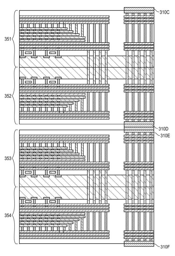
[0041] FIGS. 3A and 3B illustrate examples of different techniques for stacking and connecting the bonded 3D flash storage dies in the package.
【0041】
  図3Aおよび3Bは、3Dフラッシュストレージの接合されたダイを、パッケージ内に積層および接続するための異なる技術の例を示す。

 FIG. 3A illustrates staggered dies and FIG. 3B illustrates an example of vertically stacked dies with emulated vias to connect the dies at the package level. 
図3Aは、ジグザグ(スタガード)に配置されたダイを示し、図3Bは、パッケージレベルの箇所にあるダイを接続するためのエミュレーションビアを用いて、縦積層されたダイの例を示す。


(*FIG. 3B;laminateとは言えない印象)

FIGS. 3A and 3B each illustrate four 3D flash storage dies (or two die pairs).
図3Aおよび3Bはそれぞれ、4つの3Dフラッシュストレージダイ(または、2対のダイ)を示す。


Similarly, the dies 351 and 352 of FIG. 3B and dies 353 and 354 are bonded together via wafer bonding techniques.
同様に、図3Bのダイ351および352同士、並びにダイ353および354同士は、ウェハボンディング技術により接合されている。

In the examples illustrated in FIGS. 3A and 3B, the dies are bonded together with their respective CMOS circuitry facing one another, such as in FIGS. 1A and 2A.
図3Aおよび3Bに示す例においては、ダイ同士は、図1Aおよび2Aのように、それらのそれぞれのCMOS回路が互いに対面する状態で接合されている。

US10950733
[0040] Referring to FIG. 5A, a semiconductor device 500 includes one or more vertically stacked germanium nanowires ( 550 set) disposed above a substrate 204 .
【0030】
  図5Aを参照すると、半導体デバイス500は、基板204の上方に配置された、垂直積層された一または複数のゲルマニウムナノワイヤ(550の組)を含む。

(*laminateではない)

Embodiments herein are targeted at both single wire devices and multiple wire devices.
本明細書の複数の実施形態は、単一ワイヤのデバイスおよび複数ワイヤのデバイスの両者を目標としている。

As an example, a three nanowire-based devices having nanowires 550 A, 550 B and 550 C is shown for illustrative purposes.
例として、ナノワイヤ550A、550B、および550Cを有する3つのナノワイヤベースのデバイスが例示目的で示されている。

For convenience of description, nanowire 550 A is used as an example where description is focused on only one of the nanowires.
複数のナノワイヤのうちの1つのみに記載の焦点が当てられる場合には、記載の便宜上、ナノワイヤ550Aが例として使用される。

It is to be understood that where attributes of one nanowire are described, embodiments based on a plurality of nanowires may have the same attributes for each of the nanowires.
1つのナノワイヤの複数の特質が説明される場合、複数のナノワイヤに基づいた複数の実施形態は、複数のナノワイヤのそれぞれについて、同一の複数の特質を有するであろうことが理解されるべきである。

US10981357
[0002] It is known to make windshields by laminating a first ply of glass, a plastic interlayer, and a second ply of glass.
【0002】
  第1のガラスのプライ(ply)、プラスチック中間層、および第2のガラスのプライを積層して、風防ガラスを製造することが知られている。

Before 1960, the plies of glass used in this process were ground and polished plate glass, which has excellent freedom from distortion.
1960年以前は、この目的で使用されるガラスのプライは、研磨された板ガラスであり、これは変形に対して優れた自由度を有する。

More recently, it has been customary to use float glass from 1.1 to 4 mm thick for the first and second plies.
近年、第1および第2のプライが1.1から4mmの厚さを有するフロートガラスが、慣例的に使用されるようになっている。

The float glass is produced by a process such as that described in U.S. Pat. Nos. 3,083,551 and 3,700,542.
フロートガラスは、米国特許第3,083,551号および第3,700,542号に記載のようなプロセスにより製造される。

Although this float glass can be used to make excellent windshields, it can deform in undesirable ways for certain applications when heated.
このフロートガラスは、優れた風防ガラスの製造に使用され得るが、これは、加熱の際に、ある用途には好ましくない態様で変形し得る。

US2019305723
[0063] In this example, the flexible substrate 20 is polyimide or another polymer,
【0023】
  この実施例では、可撓性基板20は、ポリイミド又は別のポリマーであり、

the conducting layer 22 is copper (Cu) or another metal or alloy,
導電層22は、銅(Cu)又は別の金属若しくは合金であり、

and the conducting layer 22 is sandwiched between two insulating layers, namely, the flexible substrate 20 and the insulating layer 30 laminated on top of the conducting layer 22 by the adhesive 32 .
導電層22は、2つの絶縁層、すなわち、可撓性基板20と、接着剤32によって導電層22の上部に積層された絶縁層30との間で挟持されている。

In other examples, the flex circuit 18 can have more than one conducting layer 22 in a laminate structure,
別の実施例では、フレックス回路18は、積層構造において導電層22を1つより多く有してもよく、

with each of the conducting layers 22 sandwiched between two insulating layers, such as the insulating layer 30 and an additional insulating layer 30 or two additional insulating layers 30 , such that each of the conducting layers 22 provides embedded conductors for making electrical connections with the solar cells 12 .
各導電層22によってソーラーセル12との電気接続を行うための埋設型導電体が設けられるように、各導電層22は、2つの絶縁層(例えば、絶縁層30、及びさらなる絶縁層30又は2つのさらなる絶縁層30)の間で挟持される。

WO2019221771
[00100] Referring again to the pre-fractured glass laminate 300 depicted in FIG. 3,
【0087】
  再び図3に示される予め破砕されたガラス積層体300を参照すると、

it is configured such that the impact-resistant aspects of the pre-fractured composites 100 are located on each of its major sides.
該予め破砕されたガラス積層体300は、予め破砕された複合体100の耐衝撃性の態様がその主面のそれぞれに配置されるように構成されている。

As such, a pre-fractured glass laminate 300 can be employed in applications in which impacts are expected to occur on any of its sides, e.g., as in a passenger window of a vehicle, residential window, etc.
このように、予め破砕されたガラス積層体300は、例えば車両の助手席窓、住宅窓などのように、その側面のいずれかに衝撃が発生すると予想される用途に使用することができる。

Further, according to some implementations of the laminate 300,
さらには、積層体300の幾つかの実装形態によれば、

a multi-ply construction can be employed in which three or more alternating plies of a pre-fractured composite 100 and an interlayer 1 10 are laminated together into the laminate 300.
予め破砕された複合体100と中間膜110との3つ以上の交互の層がともに積層体300に積層された、多層構造を採用することができる。

Such configurations could be used in applications requiring particularly high impact resistance, such as windows in military vehicles in need of ballistic and armor protection.
このような構成は、弾道及び装甲防護を必要とする軍用車両の窓など、特に高い耐衝撃性を必要とする用途で使用することができる。


laminate:密着、隙間なし、層が薄い・・・とも限らない

stack:重ねる、隙間あり、層が厚い・・・とも限らない

コメント
  • X
  • Facebookでシェアする
  • はてなブックマークに追加する
  • LINEでシェアする

磁化回転

2021-06-25 11:09:47 | 英語特許散策

US2020278403(TDK)
[0001] The present invention relates to a spin-orbit-torque magnetization rotational element, a spin-orbit-torque type magnetoresistance effect element, and a magnetic memory.
【0001】
  本発明は、スピン軌道トルク型磁化回転素子スピン軌道トルク型磁気抵抗効果素子及び磁気メモリに関する。

Priority is claimed on Japanese Patent Application No. 2018-105393, filed May 31, 2018, the content of which is incorporated herein by reference.
本願は、2018年5月31日に、日本に出願された特願2018-105393号に基づき優先権を主張し、その内容をここに援用する。

US2020321518(TDK)
[0063] (Spin Current Magnetization Rotating Element)
【0044】
(スピン流磁化回転素子

[0064] FIG. 8 is a schematic view illustrating an example of a spin current magnetization rotating element according to one embodiment of the present disclosure. 
図8に、本発明の一実施形態に係るスピン流磁化回転素子の一例の概略模式図を示す。

FIG. 8A is a plan view, and FIG. 8B is a cross-sectional view taken along line X-X, which is a center line in a width direction of a spin-orbit torque wiring 120 in FIG. 8A.
図8Aは平面図であり、図8Bは図8Aのスピン軌道トルク配線120の幅方向の中心線であるX-X線で切った断面図である。

US2021151665(TDK)
[0002] The present invention relates to a spin-orbit torque type magnetization rotational element, a spin-orbit torque type magnetoresistance effect element, and a magnetic memory.
【0001】
  本発明は、スピン軌道トルク型磁化回転素子スピン軌道トルク型磁気抵抗効果素子及び磁気メモリに関する。

Priority is claimed on Japanese Patent Application No. 2018-002187, filed Jan. 10, 2018 in Japan, the content of which is incorporated herein by reference.
本願は、2018年1月10日に、日本に出願された特願2018-002187に基づき優先権を主張し、その内容をここに援用する。

コメント
  • X
  • Facebookでシェアする
  • はてなブックマークに追加する
  • LINEでシェアする

当ブログの例文について

本ブログの「特許英語散策」等題した部分では、英語の例文を管理人の独断と偏見で収集し、適宜訳文・訳語を記載しています。 訳文等は原則として対応日本語公報をそのまま写したものです。私個人のコメント部分は(大抵)”*”を付しています。 訳語は多数の翻訳者の長年の努力の結晶ですが、誤訳、転記ミスもあると思いますのでご注意ください。