


US10651153
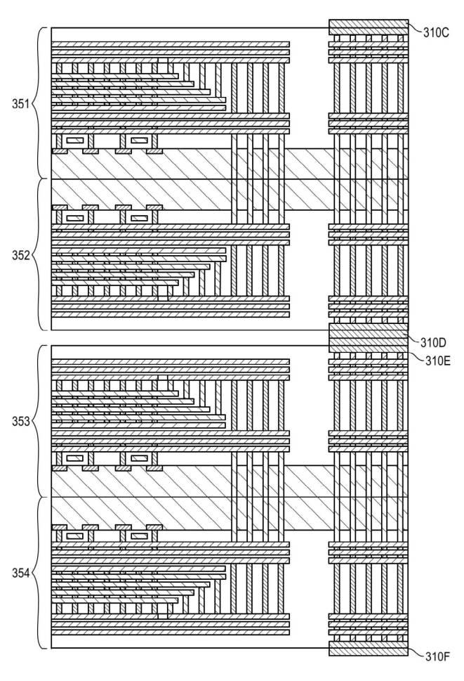
[0041] FIGS. 3A and 3B illustrate examples of different techniques for stacking and connecting the bonded 3D flash storage dies in the package.
【0041】
図3Aおよび3Bは、3Dフラッシュストレージの接合されたダイを、パッケージ内に積層および接続するための異なる技術の例を示す。
FIG. 3A illustrates staggered dies and FIG. 3B illustrates an example of vertically stacked dies with emulated vias to connect the dies at the package level.
図3Aは、ジグザグ(スタガード)に配置されたダイを示し、図3Bは、パッケージレベルの箇所にあるダイを接続するためのエミュレーションビアを用いて、縦に積層されたダイの例を示す。
(*FIG. 3B;laminateとは言えない印象)
FIGS. 3A and 3B each illustrate four 3D flash storage dies (or two die pairs).
図3Aおよび3Bはそれぞれ、4つの3Dフラッシュストレージダイ(または、2対のダイ)を示す。
Similarly, the dies 351 and 352 of FIG. 3B and dies 353 and 354 are bonded together via wafer bonding techniques.
同様に、図3Bのダイ351および352同士、並びにダイ353および354同士は、ウェハボンディング技術により接合されている。
In the examples illustrated in FIGS. 3A and 3B, the dies are bonded together with their respective CMOS circuitry facing one another, such as in FIGS. 1A and 2A.
図3Aおよび3Bに示す例においては、ダイ同士は、図1Aおよび2Aのように、それらのそれぞれのCMOS回路が互いに対面する状態で接合されている。
US10950733
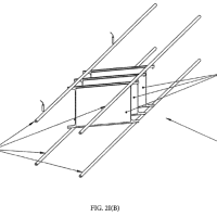
[0040] Referring to FIG. 5A, a semiconductor device 500 includes one or more vertically stacked germanium nanowires ( 550 set) disposed above a substrate 204 .
【0030】
図5Aを参照すると、半導体デバイス500は、基板204の上方に配置された、垂直に積層された一または複数のゲルマニウムナノワイヤ(550の組)を含む。
(*laminateではない)
Embodiments herein are targeted at both single wire devices and multiple wire devices.
本明細書の複数の実施形態は、単一ワイヤのデバイスおよび複数ワイヤのデバイスの両者を目標としている。
As an example, a three nanowire-based devices having nanowires 550 A, 550 B and 550 C is shown for illustrative purposes.
例として、ナノワイヤ550A、550B、および550Cを有する3つのナノワイヤベースのデバイスが例示目的で示されている。
For convenience of description, nanowire 550 A is used as an example where description is focused on only one of the nanowires.
複数のナノワイヤのうちの1つのみに記載の焦点が当てられる場合には、記載の便宜上、ナノワイヤ550Aが例として使用される。
It is to be understood that where attributes of one nanowire are described, embodiments based on a plurality of nanowires may have the same attributes for each of the nanowires.
1つのナノワイヤの複数の特質が説明される場合、複数のナノワイヤに基づいた複数の実施形態は、複数のナノワイヤのそれぞれについて、同一の複数の特質を有するであろうことが理解されるべきである。
US10981357
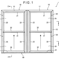
[0002] It is known to make windshields by laminating a first ply of glass, a plastic interlayer, and a second ply of glass.
【0002】
第1のガラスのプライ(ply)、プラスチック中間層、および第2のガラスのプライを積層して、風防ガラスを製造することが知られている。
Before 1960, the plies of glass used in this process were ground and polished plate glass, which has excellent freedom from distortion.
1960年以前は、この目的で使用されるガラスのプライは、研磨された板ガラスであり、これは変形に対して優れた自由度を有する。
More recently, it has been customary to use float glass from 1.1 to 4 mm thick for the first and second plies.
近年、第1および第2のプライが1.1から4mmの厚さを有するフロートガラスが、慣例的に使用されるようになっている。
The float glass is produced by a process such as that described in U.S. Pat. Nos. 3,083,551 and 3,700,542.
フロートガラスは、米国特許第3,083,551号および第3,700,542号に記載のようなプロセスにより製造される。
Although this float glass can be used to make excellent windshields, it can deform in undesirable ways for certain applications when heated.
このフロートガラスは、優れた風防ガラスの製造に使用され得るが、これは、加熱の際に、ある用途には好ましくない態様で変形し得る。
US2019305723
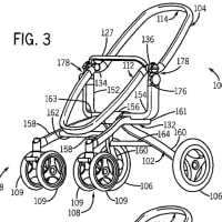
[0063] In this example, the flexible substrate 20 is polyimide or another polymer,
【0023】
この実施例では、可撓性基板20は、ポリイミド又は別のポリマーであり、
the conducting layer 22 is copper (Cu) or another metal or alloy,
導電層22は、銅(Cu)又は別の金属若しくは合金であり、
and the conducting layer 22 is sandwiched between two insulating layers, namely, the flexible substrate 20 and the insulating layer 30 laminated on top of the conducting layer 22 by the adhesive 32 .
導電層22は、2つの絶縁層、すなわち、可撓性基板20と、接着剤32によって導電層22の上部に積層された絶縁層30との間で挟持されている。
In other examples, the flex circuit 18 can have more than one conducting layer 22 in a laminate structure,
別の実施例では、フレックス回路18は、積層構造において導電層22を1つより多く有してもよく、
with each of the conducting layers 22 sandwiched between two insulating layers, such as the insulating layer 30 and an additional insulating layer 30 or two additional insulating layers 30 , such that each of the conducting layers 22 provides embedded conductors for making electrical connections with the solar cells 12 .
各導電層22によってソーラーセル12との電気接続を行うための埋設型導電体が設けられるように、各導電層22は、2つの絶縁層(例えば、絶縁層30、及びさらなる絶縁層30又は2つのさらなる絶縁層30)の間で挟持される。
WO2019221771
[00100] Referring again to the pre-fractured glass laminate 300 depicted in FIG. 3,
【0087】
再び図3に示される予め破砕されたガラス積層体300を参照すると、
it is configured such that the impact-resistant aspects of the pre-fractured composites 100 are located on each of its major sides.
該予め破砕されたガラス積層体300は、予め破砕された複合体100の耐衝撃性の態様がその主面のそれぞれに配置されるように構成されている。
As such, a pre-fractured glass laminate 300 can be employed in applications in which impacts are expected to occur on any of its sides, e.g., as in a passenger window of a vehicle, residential window, etc.
このように、予め破砕されたガラス積層体300は、例えば車両の助手席窓、住宅窓などのように、その側面のいずれかに衝撃が発生すると予想される用途に使用することができる。
Further, according to some implementations of the laminate 300,
さらには、積層体300の幾つかの実装形態によれば、
a multi-ply construction can be employed in which three or more alternating plies of a pre-fractured composite 100 and an interlayer 1 10 are laminated together into the laminate 300.
予め破砕された複合体100と中間膜110との3つ以上の交互の層がともに積層体300に積層された、多層構造を採用することができる。
Such configurations could be used in applications requiring particularly high impact resistance, such as windows in military vehicles in need of ballistic and armor protection.
このような構成は、弾道及び装甲防護を必要とする軍用車両の窓など、特に高い耐衝撃性を必要とする用途で使用することができる。
laminate:密着、隙間なし、層が薄い・・・とも限らない
stack:重ねる、隙間あり、層が厚い・・・とも限らない


※コメント投稿者のブログIDはブログ作成者のみに通知されます