US10655551
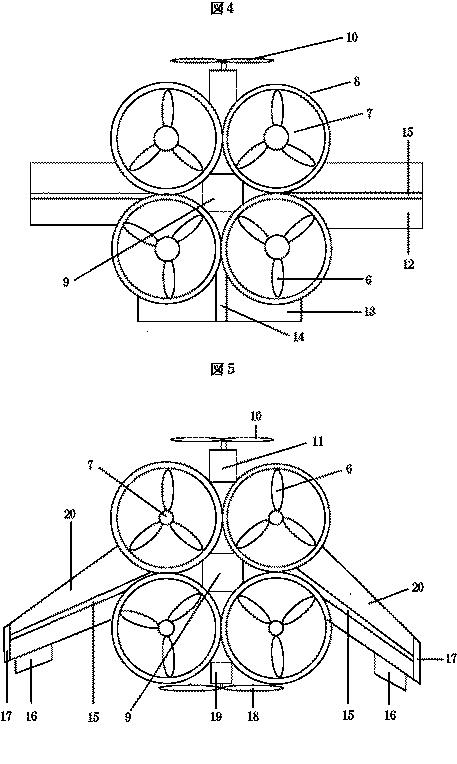
[0074] FIGS. 3 to 6 show different views of a part of a variator embodying the invention.
【0049】
図3~6は、本発明の実施形態の可変装置の一部分を異なった場所からの眺めを示す。
The variator comprises an input race 10 , shaped generally as an annulus.
この可変装置は、一般的には環状である入力軌道輪10を備えている。
The input race 10 has an inner surface within which annular recess 12 of arcuate cross-section is formed to provide a working surface of the input race 10 .
この入力軌道輪10は内周面を有しており、内周面の内側には、入力軌道輪10の作用面を提供するように弓形断面の環状凹部12が形成されている。
The variator further comprises an output race 14 , shown in dotted lines only in FIG. 4 that is substantially similar to the input race 10 .
この可変装置は、入力軌道輪10とほぼ同じであり、図6において破線で示された出力軌道輪14をさらに備えている。
The input race 10 and the output race 14 are disposed coaxially on a variator axis V, with their working surfaces facing one another, thus forming a toroidal cavity between the races 10 , 14 that is bounded by their working surfaces.
入力軌道輪10と出力軌道輪14は、可変装置の軸V上に同軸に配置されており、それらの作用面は互いに対向し、それによって、これらの軌道輪10と14の間に、これらの作用面によって結合されたトロイダルキャビティーを形成する。
Each of the races 10 , 14 is mounted for rotation about the variator axis V.
各軌道輪10及び14は、それぞれ可変装置の軸Vに対して回転するように取り付けられている。
EP1597495
Referring to Figure 2, a conical spring 133, positioned between the input shift guide 13a and stator 80a biases the shifting of the transmission 100 toward low.
【0052】
図2を参照すると、入力シフトガイド13aと固定子80aの間に位置決めされた円錐型ばね133は、変速機100をローにシフトするようにバイアスを付与する。
Referring to Figure 1, output disc bearings 102, which contact a bearing race near the perimeter of the output disc 101, absorb and transfer axial force generated by the transmission 100 to the case 40.
図1を参照すると、出力ディスク101の周囲の付近で軸受けの軌道輪と接触する出力ディスク軸受け102が、変速機100によって生成された軸力を吸収し、ケース40に伝達する。
The case 40 has a corresponding bearing race to guide the output disc bearings 102.
ケース40は対応する軸受けの軌道輪を有して、出力ディスク軸受け102を案内する。
WO2006086704
[00126] In the illustrated example, the one-way clutch 594 includes a portion have the first gear pinion 570 formed thereon and an adjacent race portion 598.
0104】
図示の実施例においては、ワンウェイクラッチ594は、第1ギヤピニオン570が形成された部分と、隣接する軌道輪の部分598とを含む。
A set of one-way clutch bearings 596 are positioned between the race portion 598 of the oneway clutch 594 and the odd iayshaft 520.
1組のワンウェイクラッチ軸受け596が、ワンウェイクラッチ594の軌道輪部分598と奇数番号のレイシャフト520との間に装着される。
When the input shaft 524 drives both the odd layshaft 520 and the even layshaft 522 for rotation up to a preselected maximum rotational speed,
入力軸524が、奇数番号のレイシャフト520および偶数番号のレイシャフト522を、予め選択された最大回転速度まで回転駆動すると、
the one-way clutch bearings 596 will frictionally engage between the race portion 598 of the one-way clutch 594 and the odd layshaft 520
ワンウェイクラッチ軸受け596が、ワンウェイクラッチ594の軌道輪部分598と奇数番号のレイシャフト520との間を摩擦係合して、
to cause the first gear 570 to be driven for rotation by the odd layshaft 520.
第1ギヤピニオン570を奇数番号のレイシャフト520によって回転駆動する。
Once that preselected maximum rotational speed is exceeded, the one-way clutch bearings 596 are allowed to free-wheel between the race portion 598 of the one-way clutch 594 and the odd layshaft 520.
予め選択された最大回転速度を超過すると、ワンウェイクラッチ軸受け596は、ワンウェイクラッチ594の軌道輪部分598と奇数番号のレイシャフト520との間を自由回転し得るようになる。
US10060476(JP)
[0002] At any places where thrust loads are applied, for example, in automatic transmissions, air conditioner compressors, and other components in automobiles, thrust roller bearings for supporting thrust loads are placed on a case-by-case basis.
【0002】
例えば、自動車用の自動変速機、カーエアコン用コンプレッサ等においてスラスト荷重が負荷される箇所には、スラスト荷重を受けるスラストころ軸受が配置される場合がある。
Such thrust roller bearings are desired to reduce the running torque in order to improve fuel efficiency and power saving.
このようなスラストころ軸受は、低燃費化、および省力化の観点から、軸受の回転トルクの低減が望まれている。
A thrust roller bearing includes raceways arranged in the direction of the rotation axis, a plurality of needle rollers rolling on raceway surfaces of the raceways, and a cage retaining the needle rollers.
スラストころ軸受は、回転軸方向に配置される軌道輪と、軌道輪の軌道面上を転動する複数の針状ころと、複数の針状ころを保持する保持器とを備える。
Some cages are manufactured by bending a steel plate and then punching out pockets that house the rollers.
保持器は、鋼板を折り曲げた後、ころを収容するポケット抜きを行って製造される場合がある。
US10006503(JP)
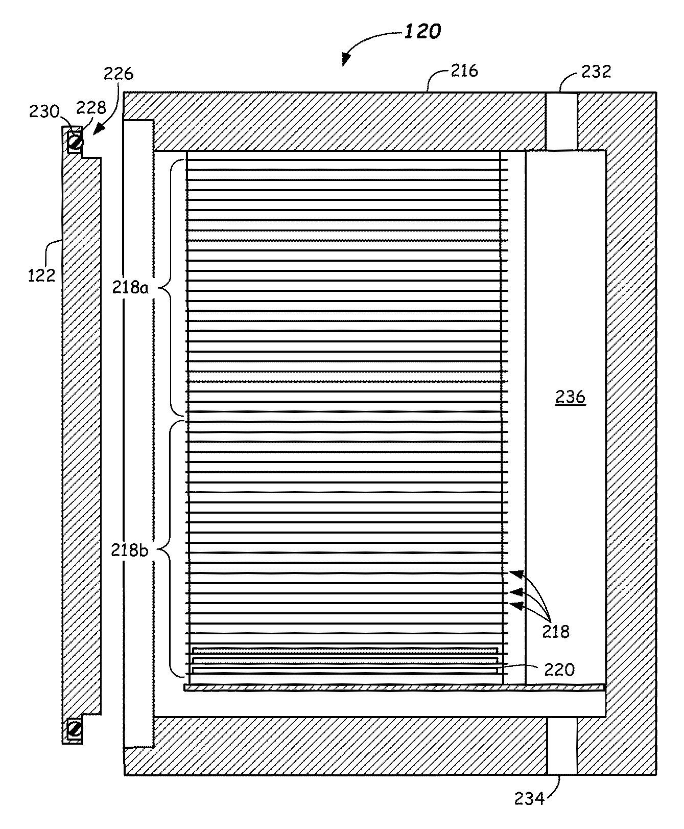
[0004] When disconnecting the clutch, any of the clutch mechanisms axially displaces the clutch release bearing device by a release fork configured to swing as a clutch pedal is stepped down.
【0004】
何れのクラッチ機構の場合も、クラッチを切る場合には、クラッチペダルの踏み込みに伴って揺動するレリーズフォークにより、クラッチレリーズ軸受装置を軸方向に変位させる。
Any one bearing ring of the release bearing configuring the clutch release bearing device is engaged to the central portion of the diaphragm spring directly or via another member, so that the central portion of the diaphragm spring is pressed or pulled.
そして、クラッチレリーズ軸受装置を構成するレリーズ軸受の何れか一方の軌道輪を、ダイヤフラムばねの中央部に、直接又は他の部材を介して係合させる事により、ダイヤフラムばねの中央部を押圧、又は引っ張る。
At this state, the clutch release bearing device prevents the respective parts from being slid and rubbed each other, based on the relative rotations of the one bearing ring and the other bearing ring, irrespective of the rotation of the diaphragm spring.
この状態でクラッチレリーズ軸受装置は、一方の軌道輪と他方の軌道輪との相対回転に基づき、ダイヤフラムばねの回転に拘らず、各部が滑り摩擦し合う事を防止する。
US10683910
[0061] Here, the axial rigidity represents a degree of difficulty of axial deformation relative to a force in the axial direction (a thrust force).
【0052】
ここで、軸方向剛性とは、軸方向の力(スラスト力)に対する軸方向変形のしづらさの度合いを表す。
In addition, a relation of “a rigidity value in the axial direction=a force required for unit deformation in the axial direction (an axial load/an amount of axial deformation” is satisfied.
また、「軸方向の剛性値=軸方向に単位変形するのに必要な力(軸方向荷重/軸方向変形量)」の関係が成り立つ。
That is, the axial rigidity of the bearing of interest represents the amount of axial displacement of this bearing.
すなわち、軸受の軸方向剛性は、軸受の軸方向変位量を表す。
The amount of axial displacement of the bearing of interest
軸受の軸方向変位量は、
represents an amount of movement (amount of axial deformation in the axial direction) of an internal ring (a rotatable bearing ring) of the rolling bearing of interest fixed to the corresponding rotational shaft when this internal ring relatively moves in the axial direction relative to an external ring (a fixed bearing ring) of the rolling bearing of interest in a state in which the external ring is fixed to the case.
転がり軸受の外輪がケースに固定されている状態で、回転軸(回転部材)に取り付けられた転がり軸受の内輪(回転可能な軌道輪)が、外輪(固定された軌道輪)に対して相対的に軸方向に移動する際の移動量(軸方向変形量)を表す。
The axial rigidity of the bearing pair of interest is obtained by synthesizing axial rigidities (summing axial rigidity values) of the two bearings.
なお、軸受対の軸方向剛性は、二つの軸受の軸方向剛性を合成(軸方向剛性値を合算)したものである。