


US2023081973(TRUMPF MASCHINEN AUSTRIA GMBH & CO KG [AT])
[0001] The invention relates to a vacuum gripping element and a vacuum gripping device which are embodied to suck and/or hold a component to be transported when subjected to a vacuum.
【0001】
本発明は、負圧を加えると搬送される部品を吸着又は保持する負圧把持要素及び負圧把持装置に関するものである。
US11364584(BYSTRONIC LASER AG [CH])
[0033] In an advantageous embodiment, the electrically conductive vacuum suction device lifts the processed parts out of the workpiece by the lifting height of the vacuum suction device.
【0030】
有利な実施形態では、導電性真空吸引装置は、真空吸引装置の持ち上げ高さによって加工された部品をワークピースから持ち上げる。
The lifting height represents the height at which the processed part is lifted or gripped from the workpiece when a vacuum is applied.
持ち上げ高さは、真空が適用されたときに加工された部品がワークピースから持ち上げられるか又は把持される高さを表す。
The height corresponds to the suction volume of the electrically conductive vacuum suction device, in particular the height corresponds to the movement potential of the suction material up to the suction nozzle.
高さは、導電性真空吸引装置の吸引体積に対応し、具体的には、高さは、吸引ノズルまでの吸引材料の移動電位に対応する。
The electrically conductive vacuum suction device is used to grip and move the processed part out of the workpiece.
導電性真空吸引装置は、加工された部品を把持してワークピースから外に移動させるために使用される。
The electrically conductive vacuum suction device does not suck onto the part, but the ambient pressure (atmospheric pressure) presses the part against the electrically conductive vacuum suction device or the electrically conductive vacuum suction device against the part of the workpiece being processed.
導電性真空吸引装置は部品を吸着しないが、周囲圧力(大気圧)が部品を導電性真空吸引装置に又は加工されるワークピースの一部に導電性真空吸着装置を押し付ける。
US9156618(MANUFACTURAS Y TRANSFORMADOS AB S L [ES])
[0016] The use of said transverse holes together with the articulating drive shafts also allows forming a flat uniform surface formed by multiple bristle brushes without needing any bottom metal guide, as occurred with the cutting mats known in the state of the art.
【0016】
上記幅方向の孔を連接駆動シャフトと共に使用することによりまた、今日の技術で知られている裁断マットに伴って見られたいかなる底部金属ガイドも必要とすることなく、複数の毛ブラシによって形成された平坦な均一の面の形成が可能になる。
This simplicity results in a huge reduction in the cost, assembly time, weight and useful height necessary for forming a vacuum chamber under the support table envisaged for suction-holding the part to be cut and conveyed.
この単純さにより、裁断され搬送される部品を吸着保持することを想定した支持テーブル下の真空チャンバの形成に必要なコスト、組み立て時間、重量および有効高さが大きく低減されることになる。
US8684168(MULTITEST ELEKTRONISCHE SYST [DE])
[0004] To hold and contact the components, handlers generally have plungers, i.e. longitudinally displaceable holding units which can hold the components, in particular by applying a suction force by means of a vacuum.
【0003】
ハンドラーは、真空による吸引力を利用して電子部品に接触しこれを保持できかつ長手方向に移動可能な保持ユニット、即ちプランジャを通常有する。
After placing the components inside the handler, the plungers are brought into a position, in which they can be advanced further toward the contact mechanisms on a linear path until the components come into contact with the contact mechanisms.
ハンドラーの内部でプランジャに電子部品を吸着した後に、電子部品は、ハンドラーにより直線経路に沿って接触装置に移送されて、接触装置に接触される。
After carrying out the test processes, the components are removed again from the test head by means of the plungers and positioned in such a way that that they can be removed from the handler by means of an unloading station and can be sorted as a function of the test result.
試験工程を実施した後に、電子部品は、再びプランジャにより試験ヘッドから除去されかつ排出位置でハンドラーから除去されて、試験結果に従って分類可能に位置決めされる。
//////
[0006] For this purpose, a central handler unit with a cuboidal central part is already known, on which a plurality of plungers is longitudinally displaceably guided, which plungers, at their front end, hold the components by means of a vacuum.
【0005】
この目的に対し、直方体形状の中央部を有するハンドラー中央ユニットが既に知られ、その中央部に接して多数のプランジャが長手方向に移動可能に案内され、プランジャの前端に電子部品が真空で吸着され保持される。
The plungers are pushed there by means of an advancing mechanism in the form of pneumatic cylinders.
空圧作動シリンダ形式の操作装置を用いてプランジャが移動される。
Although this principle has proven successful, it is difficult or very expensive to thus bring a plurality of plungers of the transport unit into the front contact position in the shortest time and in a very precise manner, and at the same time to ensure a soft, gentle contacting of the components.
この構造は、確実に動作することが実証されているが、移送ユニットの複数のプランジャを最短時間でかつ極めて正確に前方の接触位置に移動させると同時に、柔軟で丁寧な電子部品の軟接触(安全接触)を確保することは、困難であり又は多大な手間を要する。
/////////
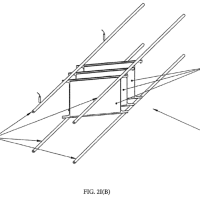
[0041] So that the heat does not flow away radially outwards in an uncontrolled manner from the circulating carriages 10 when the temperature of the components 43 is being controlled, a peripheral cover 51 in form of a stationary, annular covering plate is arranged at a slight radial spacing outside the circulating carriage 10 .
【0030】
電子部品43の温度を調節する際に、回転キャリッジ10の径方向外側に僅かな径方向の間隔をもって回転キャリッジ10の周囲に固定される薄板リング状のカバー41により、回転キャリッジ10から制御し難い熱の径方向外側の散逸を防止することができる。
The cover 51 covers the circulating carriages 10 over their entire circulating path with the exception of those regions in which the circulating carriages 10 are loaded with components 43 , unloaded, and are pushed radially outwards in the direction of the test device.
回転キャリッジ10内に電子部品43を吸着する装填領域、回転キャリッジ10から電子部品を排出する排出領域及び試験装置方向の径方向外側に電子部品を移送する試験領域を除き、カバー51は、回転キャリッジ10が回転する全周面にわたり回転キャリッジ10を覆う。
FIG. 4 shows the loading station, in which the cover plates are spaced apart from one another in the circulating direction to such an extent that the components 43 can be placed on the associated plungers 12 without hindrance. Each circulating carriage 10 can be made to rotate along the guides 9 a , 9 b by its own drive arm 13 .
図4は、周方向に切除して薄板のカバー41に装填位置で形成される開口部を示し、開口部は、対応するプランジャ12上への電子部品43の吸着を妨害しない。
US2024246184(FANUC CORP [JP])
[0025] Further, the inner diameter ID 1 of the front portion of the cylindrical member 2 is smaller than the outer diameter (or outer dimension) ED 1 of the surface of the cutting edge part 103 as the part to be changed and larger than the inner diameter (or inner dimension) ID 2 of the surface of the cutting edge part 103 .
【0017】
さらに、筒状部材2の先方部分の内径ID1は、被交換部品としての刃先部品103の表面の外径(又は外寸)ED1よりも狭く、且つ刃先部品103の表面の内径(又は内寸)ID2よりも広く構成されている。
As a result, the cylinder mouth 17 comes into contact with the surface of the cutting edge part 103 , and the surface portion of the cutting edge part 103 inside the surface portion that comes into contact with the cylindrical opening 17 is exposed to the air passage 18 , so that when the air passage 18 is sucked to a negative pressure, air is not sucked into the cylindrical member 2 , and the cylindrical member 2 can be sucked.
それにより筒口17が刃先部品103の表面に接触するとともに、筒口17に接触する刃先部品103の表面部分よりも内側の表面部分はエア導通路18に対して露出するので、エア導通路18を負圧に吸引したときに、筒状部材2に吸い込まれることなく、筒状部材2を吸着させることが可能になる。
[0026] Note that the transverse sectional shape of the rear portion of the cylindrical member 2 is a circle so as not to hinder the axial rotation of the driver bit 4 , whereas the transverse sectional shape of the front portion of the cylindrical member 2 , which constitutes the air passage 18 , is typically a circle, but may be a polygon such as a triangle or a square.
【0018】
なお、筒状部材2の後方部分の横断面形状はドライバービット4の軸回転を阻害しないように円形であるが、エア導通路18を構成する筒状部材2の先方部分の横断面形状は典型的には円形であるが、三角形や四角形等の多角形であってもよい。
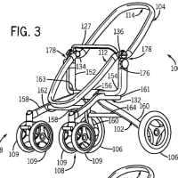
[0027] A circular opening 24 is formed in the side wall of the front portion of the cylindrical member 2 .
【0019】
筒状部材2の先方部分の側壁には円形の開口24があけられている。
The opening 24 communicates with the air passage 18 , and a tubular air connection portion 25 is attached to the opening 24 so as to face outward.
開口24はエア導通路18に連通しており、開口24には管状のエア接続部25が外向きに取り付けられている。
As shown in FIG. 5 , an air hose 41 is connected to the air connection portion 25 , and an air pump device (vacuum pump device) 40 is connected to the opposite side of the air hose 41 .
図5に示すように、エア接続部25にはエアホース41が接続され、エアホース41の反対側はエアポンプ装置(真空ポンプ装置)40が接続されている。
Air is drawn from the air passage 18 by the air pump device 40 .
エアポンプ装置40により、エア導通路18からエアが吸引される。
As a result, a negative pressure is generated in the air passage 18 , and the cutting edge part 103 can be sucked together with the screw 104 .
それによりエア導通路18に負圧が発生し、刃先部品103をネジ104とともに吸着することができる。
US2024244817(YAMAHA MOTOR CO LTD [JP])
[0003] Conventionally, a component mounting system has been known that is equipped with a mounting apparatus that obtains a component loading board by loading electronic components (hereinafter simply referred to as “component”) on a board such as a printed circuit board.
【0002】
従来から、プリント基板等の基板上に電子部品(以下、単に「部品」という)を搭載して部品搭載基板を得る実装機を備えた部品実装システムが知られている。
In this kind of component mounting system, the mounting apparatus includes a feeder that executes a component supply process to supply the component, a suction nozzle that executes a component suction process to suck the component supplied by the feeder, and a loading head that executes a component loading process to load the component on the board.
この種の部品実装システムにおいて実装機は、部品を供給する部品供給処理を行うフィーダーと、フィーダーにより供給された部品を吸着する部品吸着処理を行う吸着ノズルを有し、部品を基板に搭載する部品搭載処理を行う搭載ヘッドと、を備える。
The loading head executes the component loading process on each of a plurality of target loading positions that is set in advance on the board.
搭載ヘッドは、基板に予め設定された複数の目標搭載位置の各々に対応して、前記部品搭載処理を行う。


※コメント投稿者のブログIDはブログ作成者のみに通知されます