


US2020379568
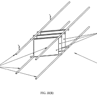
[0049] In the present invention, signaling on the panel may be controlled by pulsing the Tx electrodes 12 in a bipolar manner.
【0036】
本発明において、パネル上のシグナリングは、Tx電極12を双極方式でパルス駆動することによって制御することができる。
This means that at each measurement, there is one or more Tx electrode 12 pulsed in a positive direction, and an equal number of Tx electrodes 12 pulsed simultaneously in a negative direction.
これは、各測定において、正の方向においてパルス駆動する1つ以上のTx電極12、及び負の方向において同時にパルス駆動する等しい数のTx電極12が存在することを意味する。
In a preferred embodiment, the positive and negative Tx electrodes 12 are adjacent (if Tx_n is positive-going, then Tx_n−1 is negative going),
好ましい実施形態において、正の及び負のTx電極12は、隣接しており(Tx_nが正の向きである場合、Tx_n-1は負の向きである)、
and the sensing pulses are cycled through Tx electrodes 12 sequentially, with a measurement on the Rx lines 14 made for each pulse.
検知パルスは、順次Tx電極12を通して循環し、各パルスごとにRxライン14に対する測定が行われる。
US2021113099
[0279] FIGS. 47C-47E compares the HR, RR and body orientation measurements from gold standard and mechano-acoustic devices throughout a sample ˜7 hrs sleep study on a male subject.
【0224】
図47C~図47Eは、男性被験者を対象とした約7時間の睡眠試験全体を通した黄金律デバイスおよび機械音響デバイスからHR、RR、身体方向測定を比較したものである。
FIG. 47C compares the HR analyzed from 60-s, 50% overlapped time windowed band-passed (1-50 Hz) EKG signals versus band-passed (20-50 Hz) mechano-acoustic z-axis signals.
図47Cは、60秒、50%オーバーラップした時間窓の帯域通過(1~50Hz)EKG信号対帯域通過(20~50Hz)機械音響z軸信号から分析されたHRを比較したものである。
FIG. 47D shows the RR analyzed from 120-s, 50% overlapped time windowed PTAF signal and device z-axis signals, applied with the bandpass filter (f1 =0.1 Hz, f2 =0.8 Hz).
図47Dは、帯域通過フィルタ(f1=0.1Hz、f2=0.8Hz)を適用した120秒、50%オーバーラップした時間窓のPTAF信号およびデバイスz軸信号から分析されたRRを示している。
Golden standard body orientation is investigated by visual inspection.
黄金律身体方向は、目視検査によって調査される。
The device captures body orientation by measuring quasistatic gravity projection in device frame, which is associated to the core-body frame (See SI for details).
デバイスは、コアボディフレームに関連付けられているデバイスフレーム内の準静的重力投影を測定することによって、身体方向を捕捉する(詳細はSIを参照)。
FIG. 47E shows that the device captures the general trend of body orientation as the rotation angle around the longitudinal axis, where we define zero degree as supine and the positive sense as turning right.
図47Eは、ゼロ度を仰臥位と定義し、正の向きを右向きと定義した場合に、デバイスが身体方向の一般的な傾向を縦軸の周りの回転角度φとして捕捉することを示している。
US10670394
The change in the magnitude of the gradient 308 along the direction of a contour line 310 indicates convergence if the gradient magnitude increases, or divergence if the gradient magnitude decreases.
等高線310の方向に沿った勾配308の大きさにおける変動は、勾配の大きさが増加するならば縮小を示し、又は勾配の大きさが減少するならば拡大を示す。
The change in gradient magnitude is affected both by the fiber angles specified in the fiber angle definition 226 (e.g., FIGS. 4, 5, and 7) and by the surface contour (e.g., the amount of surface curvature) of the surface definition 214 ( FIG. 6) of the composite ply 202 .
勾配の大きさにおける変動は、繊維角度定義226(例えば、図4、図5、及び図7)において特定された繊維角度、及び、複合材プライ202の表面定義214(図6)の表面の輪郭(例えば、表面の湾曲の量)、の両方によって影響を受ける。
[0059] Mathematically, the process of determining a magnitude function ƒ to scale the third unit vector field Y may be described using the fact that on a simply connected surface M, a vector field is the gradient of a potential function if and only if the curl of the vector field vanishes.
【0023】
数学的に、第3単位ベクトル場Yーをスケーリングするための大きさ関数fを決定するプロセスは、単純に連結された表面M上で、ベクトル場の巻きが消えるならば、消えさえするならば、ベクトル場がポテンシャル関数の勾配であるという事実を使用して説明され得る。
For a discrete vector field, the result is analogous.
離散したベクトル場に対して、その結果は類似している。
Defining some terminology, a discrete vector field Y on a triangulated surface approximation Mh with n triangles comprises a tuple of vectors:
幾つかの用語を定義すると、n個の三角形を有する三角形に分割された表面の近似Mh上の離散したベクトル場Yは、以下のベクトルのタプルを含む。
Y=(Y0 , . . . , Yn−1 ) where Yj is a vector in the plane defined by the triangle tj .
すなわち、Y=(Y0、…、Yn-1)である。ここで、Yjは、三角形tjによって規定される平面内のベクトルである。
For a triangulated surface 218 having triangles ti and tj (not shown) with a common edge e oriented positively in ti , define:
tiにおいて正の向きの共通のエッジeを有する(図示せぬ)三角形ti及びtjを有する三角形を有する三角形に分割された表面218に対して、以下を定義する。
US10649523
[0023] As shown in the sche 101782-006810US-1091827 atic representation in FIG. 2 the 2D optical sensor arrays 122 , 124 , 126 are displaced from the Cartesian coordinate system origin.
【0022】
図2における略図に示されるように、2D光学センサアレイ122、124、126は、デカルト座標系原点から変位される。
In the augmented reality headgear 104 , the 2D optical sensor arrays are displaced from the effective center of rotation for head movements which is located in the vicinity of the back of the user's neck.
拡張現実ヘッドギヤ104では、2D光学センサアレイは、ユーザの頸部の背後の近傍に位置する、頭部移動に関する事実上の回転中心から変位される。
Rotations about the X, Y and Z axes are sensed by sensing shifts of the speckle patterns produced on the 2D optical sensor arrays 122 , 124 , 126 .
X、Y、およびZ軸を中心とする回転は、2D光学センサアレイ122、124、126上で作られたスペックルパターンの偏移を感知することによって感知される。
A component of rotation about a given axes (X, Y or Z) will induce a speckle shift that is azimuthal with respect to the given axes on the 2D optical sensor arrays 122 , 124 or 126 other than the 2D optical sensor array 122 , 124 or 126 facing in a direction parallel to the given axis.
所与の軸(X、YまたはZ)を中心とする回転の成分は、所与の軸と平行方向を向いた2D光学センサアレイ122、124または126以外の2D光学センサアレイ122、124、または126上の所与の軸に対する方位角である、スペックル偏移を誘発するであろう。
(For the present purposes the positive sense of rotation about the positive Cartesian axes is defined using the right hand rule.)
(本目的のために、正のデカルト軸を中心とする回転の正の向きは、右手の法則を使用して定義される。)
Thus for example the −X direction is azimuthal with respect to the Z-axis on the sideways (+Y) facing 2D optical sensor array 124 and the +Y direction is also azimuthal with respect to the Z-axis on the front (+X) facing 2D optical sensor array 126 .
したがって、例えば、-X方向は、側方(+Y)を向いた2D光学センサアレイ124上のZ-軸に対する方位角であって、+Y方向もまた、正面(+X)を向いた2D光学センサアレイ126上のZ-軸に対する方位角である。
US10953675
[0276] Considering FIG. 9, in which the line R shows the resultant force shown in FIG. 7,
【0249】
線Rが、図7に示している合力を示す図9に注目すると、
the line RP shows a resultant force which is generated by the combination of the spring 28 , the permanent magnet 27 and the electromagnet 23 , when the coil 24 is energised with a current of three amps in a positive sense (+3 A).
線RPが、コイル24が正の向きの3アンペア(+3A)の電流で励磁された時にばね28と永久磁石27と電磁石23との組み合わせが発生させた合力を示している。
It can be seen that the line RP is a shifted version of the line R—the shift being a result of the additional force generated by the electromagnet 23 in the direction C (as indicated in FIGS. 5 to 8).
線RPは線Rがずれたものであり、このずれは、電磁石23が方向C(図5から図8に示している)に発生させる更なる力の結果であることがわかる。
Thus, it will be appreciated that, whatever the position of the printhead 4 , if a current of plus three amps is caused to flow in the coil 24 ,
上記のことから、印刷ヘッド4の位置がどのようなものであっても、プラス3アンペアの電流がコイル24内に流された場合には、
the resultant force will be in the direction C, and will cause the printhead 4 to be urged towards the printing surface 11 .
合力は方向Cにあることになり、これにより印刷ヘッド4は印刷面11に向かって付勢されることになることは理解されるであろう。
US11378502
[0087] FIGS. 18-23 show multiple embodiments of residual substrate surfaces 17 containing micromodifications, along with characterization techniques utilizing contact or non-contact residual substrate surface measurement devices.
【0061】
図18-23は、接触または非接触残留基板表面測定デバイスを利用する特性評価技法とともに、微細修正を含む残留基板表面17の複数の実施形態を示す。
FIGS. 18-20 are shown with a non-contact residual substrate surface measurement device 91 , while FIGS. 21-23 are shown with a contact residual substrate surface measurement device 93 .
図18-20が、非接触残留基板表面測定デバイス91を伴って示されている一方で、図21-23は、接触残留基板表面測定デバイス93を伴って示されている。
In FIGS. 18, 19, 21, and 22, micromodifications result from a stylus operating in a frictional sliding mode, with the orientation of the micromodification dependent on the stylus geometry and orientation.
図18、19、21、および22では、微細修正は、摩擦スライドモードで動作するスタイラスに起因し、微細修正の向きは、スタイラス幾何学形状および向きに依存する。
FIGS. 18 and 21 show residual substrate surfaces 17 from contact mechanics tests in the transverse direction of the material, whereas
図18および21が、材料の横方向における接触力学試験からの残留基板表面17を示す一方で、
FIGS. 19 and 22 show residual substrate surfaces 17 from contact mechanics tests in the short transverse direction, which is perpendicular to the substrate surface.
図19および22は、基板表面と垂直である短横方向における接触力学試験からの残留基板表面17を示す。


※コメント投稿者のブログIDはブログ作成者のみに通知されます