goo blog サービス終了のお知らせ 

和英特許翻訳メモ

便利そうな表現、疑問、謎、その他メモ書き。思いつきで書いてます。
拾った用例は必ずしも典型例、模範例ではありません。

画像に展開

2021-07-20 12:53:55 | 英語特許散策

WO2017092973
Execution of the machine-executable instructions further cause the processor to determine an extended SENSE equation at least partially using the at least one image artifact origin.
【0026】
  マシン実行可能命令の実行により、プロセッサは更に、少なくとも部分的には少なくとも1つの画像アーチファクト発生源を使用して、拡張されたSENSE式を決定する。

During SENSE image reconstruction images acquired from each of the multiple antenna elements are reconstructed and then combined, unfolded into a single image
SENSE画像の再構成中に、複数のアンテナ素子の各々から取得された画像が再構成され、次いで組み合わせられ、単一の画像に展開される。

コメント
  • X
  • Facebookでシェアする
  • はてなブックマークに追加する
  • LINEでシェアする

ショットピーニング

2021-07-19 14:53:48 | 英語特許散策

WO2015123673
Shot peening is a mechanical surface treatment having the objective of enhancing the resistance of mostly metallic components or workpieces that are subjected to cyclic loadings, wear, and corrosion and other life time reducing influences.
【0003】
  ショットピーニングは、繰返し荷重、摩耗、及び腐食と、その他の寿命を短縮する作用の下に供される、ほとんど金属の構成要素又は加工物の、耐性を高める目的を持つ機械的表面処理である。

During the shot peening process, the abrasive medium, also called shot medium, is propelled onto the surface of a workpiece. The impact of the medium dimples the surface of the workpiece.
ショットピーニングプロセス中、ショット媒体とも呼ばれる研磨媒体を、加工物の表面へと推進させる。媒体の衝撃が、加工物の表面に窪みを作る

The restoring force below the dimple in the workpiece results in a hemisphere of material that is relatively highly stressed in compression and a compressive residual stress field develops over the peened surfaces as the dimples overlap during the peening process.
加工物の窪みの下の復元力は、圧縮で比較的高い応力がかかった材料の半球をもたらし、ピーニングプロセス中に窪みが重なるにつれて、ピーニングされた表面全体に圧縮残留応力場が発生する。

Such generated compressive stresses can provide a wide variety of benefits to a workpiece.
そのような発生した圧縮応力は、広く様々な利益を加工物に提供することができる。

For example, the useful life time of a workpiece may be increased under cyclical loads or stresses caused by corrosion from stress cracking, friction, cavitation, galling, erosion and wear, as well as combinations of these kinds of stresses.
例えば、加工物の有用な寿命は、応力亀裂による腐食、摩擦、キャビテーション、かじり、浸食、及び摩耗、並びにこれらの種類の応力の組合せによって引き起こされた、繰り返される荷重又は応力の下で延びる可能性がある。

It is commonly assumed that these benefits are caused by the presence of the compressive stresses on the surface of the workpiece, since such stresses reduce the tendency of surface crack formation and or crack propagation.
一般にこれらの利益は、加工物の表面での圧縮応力の存在によって引き起こされると想定されるが、それはそのような応力が、表面亀裂形成又は亀裂伝搬の傾向を低減させるからと考えられる。

WO2013166029
Impacting the surface of the wire 396, 397 used for creating the torsion springs 134, 136 with projectiles, or 'shot peening' is used to put residual compressive stress in the surface of the wire 396, 397.
【0150】
  ねじりバネ134、136を形成するためのワイヤ396、397の表面に投射を衝突させること、または「ショットピーニング」が、ワイヤ396、397の表面に残留圧縮応力を付加するために使用される。

The wire 396, 397 is then wound into the torsion springs 134, 136.
次いで、ワイヤ396、397は、巻回されてねじりバネ134、136となる。

Due to their shot peening, the resulting torsion springs 134, 136 can now accept more tensile stress than identical springs made without shot peening.
このようなショットピーニングにより、結果として生じるねじりバネ134、136は、ショットピーニングを行うことなく形成された同等のバネよりも大きな引張応力を受け入れることが可能となる。

US2020206871(JP)
[0007] An apparatus for treating a surface of a first aspect of the present invention that treats an object to be processed while transporting the object on a line for treating a surface,
【0006】
  本発明の第1の態様に係る表面処理装置は、被処理対象物を表面処理ラインで送りながら処理する表面処理装置であって、

wherein the line for treating the surface includes an area for pre-cleaning, an area for projecting, and an area for post-cleaning,that are arranged from an upstream side.
前記表面処理ラインには上流側から前洗浄エリア、投射エリア、後洗浄エリアを含み、

The apparatus has a first cleaning device that cleans the object to be processed at the area for pre-cleaning.
前記前洗浄エリアにおいて被処理対象物を洗浄する第一洗浄装置と、

It also has a shot-peening machine that carries out shot peening by shooting shots on the object to be processed at the area for projecting.
前記投射エリアにおいて被処理対象物に対して投射材を投射してショットピーニング処理を施すショットピーニング装置と、

It also has a second cleaning device that cleans the object to be processed at the area for post-cleaning.
前記後洗浄エリアにおいて被処理対象物を洗浄する第二洗浄装置と、

It also has first detecting devices that count, at upstream sides of the line for treating a surface of the area for pre-cleaning, the area for projecting, and the area for post-cleaning, a number of objects to be processed that are carried into the respective areas and that detect the conditions of the surfaces of the objects to be processed.
前記前洗浄エリア、前記投射エリア、及び前記後洗浄エリアの各々における前記表面処理ラインの上流側において、各エリアに搬入される被処理対象物の個数をそれぞれカウントすると共にその被処理対象物の表面の状態を検出する第一検出装置と、

It also has second detecting devices that count at downstream sides of the line for treating a surface of the area for pre-cleaning, the area for projecting, and the area for post-cleaning, a number of objects to be processed that are carried out of the respective areas and that detect the conditions of the surfaces of the objects to be processed.
前記前洗浄エリア、前記投射エリア、及び前記後洗浄エリアの各々における前記表面処理ラインの下流側において、各エリアから搬出された被処理対象物の個数をそれぞれカウントすると共にその被処理対象物の表面の状態を検出する第二検出装置と、を有する。

WO2017075234
[191] In a third work area 1724c, a peening process may be manually or robotically applied to one or more parts.
【0139】
  第3の作業領域1724cにおいて、ピーニング工程が1つ以上の部品に手動又はロボット制御で適用されてもよい。

For example, in selected embodiments, a manual or robotic system may use the same granular material (i.e., the same granular material used to create the parts) as a shot media in a peening process to improve a surface finish of the parts.
例えば、選りすぐりの実施形態では、手動又はロボットシステムは、部品の表面仕上げを向上させるためのピーニング工程において、投射材と同じ粒状材料(すなわち、部品を作り出すために用いられた同じ粒状材料)を用いてもよい。

US2021129290(JP)
[0047] The loading chamber 20 A is a chamber for use in loading of a workpiece W into the cabinet 12 . The unloading chamber 20 B is a chamber for use in unloading of the workpiece W from the cabinet 12 .
【0039】
  搬入室20Aは、被処理対象物Wをキャビネット12に搬入するための室である。搬出室20Bは、被処理対象物Wをキャビネット12から搬出するための室である。

The inspection chamber 22 A is a chamber for use in inspection of surface properties of the workpiece W before being subjected to shot peening.
検査室22Aは、ショットピーニング処理が行われる前の被処理対象物Wの表面特性を検査するための室である。

The inspection chamber 22 B is a chamber for use in inspection of the surface properties of the workpiece W after being subjected to shot peening.
検査室22Bは、ショットピーニング処理が行われた後の被処理対象物Wの表面特性を検査するための室である。

The shot chambers 24 A and 24 B are chambers in which the shot media is ejected to the workpiece W.
投射室24A,24Bは、投射材が被処理対象物Wに投射される室である。

In a lower section of the inside of the cabinet 12 , a product placement part 18 is provided on which the workpiece W is placed. Details of the product placement part 18 will be described later.
キャビネット12の内部における下部には、被処理対象物Wが載置される製品載置部18が設けられている。製品載置部18については詳細後述する。

コメント
  • X
  • Facebookでシェアする
  • はてなブックマークに追加する
  • LINEでシェアする

窒化処理

2021-07-19 14:09:25 | 英語特許散策

US9067833
[0013] Hattori et al. (U.S. 2006/0283290) describe silica coated, nitrided iron particles having an average particle diameter of 5 to 25 nm.
【0011】
  服部ら(米国特許出願公開第2006/0283290号)は、窒化処理した平均粒径が5~25nmの鉄粒子をシリカで被覆したもの記載している。

The particles are “substantially spherical” and are useful for magnetic layers such as a magnetic recording medium.
この粒子は、「実質的に球形」であり、磁気記録媒体などの磁性層に役立つ。

US6676724
The present invention resides in an improved powder metal engine component particularly suited for use as a valve seat insert.
【0015】
  本発明は弁座インサートとしての使用に特に適した改良された粉末金属エンジン構成要素に属する。

The powder metal valve seat insert according to the present invention offers superior properties of abrasive and adhesive wear resistance, high temperature resistance, hot hardness and machinability.
本発明による粉末金属弁座インサートは、耐アブレシブ磨耗および耐凝着摩耗、耐高温性、熱間硬度および機械加工性について優れた特性を示す。

The powder metal valve seat insert in accordance with the present invention is useful in a wide variety of internal combustion engine applications such as in a heavy duty truck application or even in a light duty passenger car application.
本発明による粉末金属弁座インサートは、重荷重のトラック用途あるいは場合によっては軽荷重の乗用車用途などの広範囲の内燃機関応用に有用である。

It can be employed with various types of valve materials including hard-faced and nitrided valves.
これは表面硬化処理および窒化処理した弁を含む様々なタイプの弁材質に用いることができる。

US9793098
Second module 158 ionitrides the substrate surfaces to be coated in nitrogen or argon-nitrogen mix RAAD plasma generated between the cathode in a shielded cathode chamber and remote anode. 
第2のモジュール178は、シールドされた陰極チャンバー内の陰極と遠隔陽極との間に生成された窒素、又はアルゴン窒素混合物の遠隔陽極アーク放電(RAAD)プラズマ中で、被覆される基板表面をイオン窒化処理する

WO2010144789
In other aspects, the upper mold surface comprises a nickel-iron alloy having a coefficient of thermal expansion of at most 5.O x 10"6 in/in/°F at temperatures between 100° and 500°F that has undergone a nitriding treatment.
【0023】
  他の態様では、金型上面は、100°乃至500°Fの温度で最大5.0×10⁻⁶in/in/°Fの熱膨張係数を有する、窒化処理された鉄ニッケル系合金を含有する。

In certain of these aspects, the nitriding treatment is ion nitriding.
特定のこれらの態様では、この窒化処理は、イオン窒化処理である。

WO2010144786
In certain aspects, the grain texture has a depth of 0.005 to 1.0 mm, and in other aspects, the grain texture has a depth of 0.1 to 0.4 mm.
【0038】
  特定の態様では、シボ構造は、0.005乃至1.0mmの深さを有し、他の態様では、このシボ構造は、0.1乃至0.4mmの深さを有する。

In certain aspects, the surface treatment comprises ion nitriding the upper mold surface.
【0039】
  特定の態様では、この表面処理は、金型上面をイオン窒化処理するステップを含む。
 
In other aspects, the surface treatment comprises aluminizing the upper mold surface and then nitriding the upper mold surface.
他の態様では、この表面処理は、金型上面をアルミメッキし、その後金型上面を窒化処理するステップを含む。
コメント
  • X
  • Facebookでシェアする
  • はてなブックマークに追加する
  • LINEでシェアする

制御を解除

2021-07-19 10:35:19 | 英語特許散策

EP2941215
[0054] In one embodiment, the exit boundary 64 is planar, located a distance L from entry boundary 50 (see FIG. 7A), and has an exit normal 59.
【0038】
  一実施形態では、終了境界64は、開始境界50(図7A参照)から距離Lだけ離れた位置にある平面であり、終了法線59を有する。

During haptic control mode, the surgical system 100 continuously calculates the distance from HIP 60 to exit boundary 64.
触覚制御モードにある間、手術システム100は、HIP60から終了境界64までの距離を継続的に計算する。

Because exit normal 59 points away from the patient's anatomy, the distance from HIP 60 to the exit boundary 64 will typically be negative during performance of bone modifications (e.g. cutting, drilling).
終了法線59は、患者の人体から離れる方向を向いているので、HIP60から終了境界64までの距離は、骨の修正(例えば、切削、掘削)が行われている間は、通常、負の値を示す。

However, when the value of this distance becomes positive, haptic control is released by deactivation of haptic object 52, and the haptic device 30 enters free mode.
しかしながら、この距離の値が正の値になるとき、触覚制御は、触覚対象物52の停止により解除され、触覚装置30はフリーモードに入る。

In other embodiments, the exit boundary 64 can be curved, three-dimensional, or any configuration or shape appropriate for interacting with HIP 60 to disengage haptic control during a surgical procedure.
他の実施形態では、終了境界64は、手術中に触覚制御を解除可能な様に、曲線状、三次元、あるいは、HIP60との相互作用に適した如何なる構成や形状も採ることができる。

WO2019040888
[0044] When the gas/water valve 130 is in use, the first configuration
【0036】
[0044]  ガス/水弁130が使用中である時、第1構成は、

allows gas to pass from the control unit 150, through the gas inlet port and into a central location within the receiving cylinder between two seals on the valve stem, and exit the gas/water valve 130 to the atmosphere through the vent (also referred to as the release hole) in the center of the gas/water valve 130.
ガスが、制御ユニット150からガス入口ポートを通って弁棒における2つのシール間の受け筒内の中央位置へと移動すること、及びガス/水弁130の中央にある(放出孔とも称される)通気口を通ってガス/水弁130から大気中へ出ることを可能にする。

In some embodiments, the first configuration is the baseline or default configuration because it is the configuration maintained when the user is not actively interacting with the gas/water valve 130.
いくつかの実施形態において、第1構成は、ユーザがガス/水弁130と能動的に相互作用していない時に維持される構成であるため、ベースライン又はデフォルト構成である。

In other words, when the user completes a task, such as moving the distal portion of the endoscopic handle 110 into position related to an organ, and releases the operational controls,
言い換えると、ユーザが、例えば内視鏡ハンドル110の遠位部を器官に関連する位置へ動かすことなどの作業を完了し、動作制御を解除すると、

the gas/water valve 130 will return to the first configuration.
ガス/水弁130は、第1構成に戻る。

The gas/water valve 130 can also be maintained in the first configuration while other functions or controls of the endoscopic system 100 are being manipulated or engaged by the user.
ガス/水弁130は、ユーザによって内視鏡システム100の他の機能又は制御が取り扱われ、又は行われている間も第1構成に維持され得る。

WO2019023086
[0021] The control components 114 may be configured to outfit the instrument panel 112 for its control and monitor functions.
【0013】
    制御構成要素114は、計器パネル112をその制御及び監視機能のために取り付けるように構成されることができる。

These configurations may embody individual devices or combinations thereof.
これらの構成は、個々の装置またはそれらの組み合わせを具体化することができる。

The devices can serve to regulate flow of operating fluids (e.g., gasses and liquids) to operate the pneumatic device.
これらの装置は、作動流体(たとえば、気体及び液体)の流量を調整し、空気圧式装置を操作するように機能することができる。

Others may serve to indicate status of these operating fluids, the valve 106, and the flow of material 110.
他のものは、これらの作動流体、弁106、及び材料110の流量の状態を示すように機能することができる。

Still other may serve to override operation of the actuator 104 or the valve 106, for example, in situations where loss of pressure of the operating fluid prevents appropriate positioning of the closure member.
さらに他のものは、たとえば、作動流体の圧力損失が閉鎖部材の適切な位置決めを妨げる状況において、アクチュエータ104または弁106の操作の自動制御を解除するように機能することができる。

US8046096
[0013] In order to effectively manage the central processing unit (CPU) and memory resources of the control device in which the process control routines and analytical server are implemented,
【0014】
  プロセス制御ルーチンおよび分析サーバが実施される制御装置の中央処理装置(CPU)およびメモリ資源を効率よく管理するために、

the analytical server provides an interface to the real-time control routines to allow the control routines to make a call to request that an algorithm to be performed on a collection of process data.
分析サーバは、制御ルーチンが、プロセスデータの収集時にアルゴリズムを実行するようにとの要求に呼出しをかけることを可能にするために、実時間制御ルーチンにインターフェースを提供する。

These requests may be prioritized and queued, so that
これらの要求は優先順に編成され待ち行列に加えられ、その結果、

the analytical server is then able to execute the requested algorithms using the collected data asynchronously with respect to the operation of control routines within the control device.
分析サーバは、制御装置内の制御ルーチンの動作に関する収集データを非同期に使用して、要求されたアルゴリズムを実行することができる。

Moreover, the operation of the analytical server may be isolated from the operation of the on-line control system
なおまた、分析サーバの動作は、オンライン制御システムの動作から分離し、

to thereby free the on-line control to collect data for another learning iteration at the same time the current data is being analyzed by the analytical server.
それによって、新しいデータが分析サーバにより分析されると同時に別の学習反復用にデータを収集するためにオンライン制御を解除する。

Once the analytical server has completed the requested operation, the generated data or results are returned to the on-line control system, i.e., to the control routines.
一旦分析サーバが要求された動作を完了したならば、生成データ又は結果がオンライン制御システム(すなわち、制御ルーチン)に送り返される。

WO2017053785
FIG. 15 shows an example of a method 1500 where an obstacle-stopped motion of a dual -hinge closure can be overridden by holding an external or internal control.
【0085】
  図15は、外部または内部の制御装置を保持することによって、デュアルヒンジクロージャの障害物停止動作を無効にすることができる方法の一例1500を示す。

At 1510 the DHC is being opened. At 1520, an obstacle is contacted and/or detected.
1510でDHCが開いている。1520で、障害物が接触および/または検出される。

At 1530, the DHC is therefore stopped.
したがって、1530でDHCが停止する。

For example, this can be accompanied by a suitable alert to the driver or other passenger.
例えば、これは運転者または他の乗客への適切な警報を伴うことができる。

At 1540 at least one input control, such as an external or internal switch, is continuously actuated by the person.
1540で、外部スイッチまたは内部スイッチなどの少なくとも1つの入力制御が人によって連続的に作動される。

At 1550, the opening of the DHC continuous based on such input.
1550で、そのような入力に基づいてDHCは連続して開いている。

For example, this can allow a person to continue opening or closing the DHC if the person knows that no damage is being done, such as if the DHC moves into contact with vegetation that can safely be pushed out of the way by the DHC.
例えば、これはDHCが動いてDHCによって安全に押しのけられる植生と接触する場合など、ダメージを受けていないことを人が知っている場合に、人がDHCの開閉を継続することを可能にすることができる。

At 1560, the person releases the input control, and the DHC is therefore stopped at 1570.
1560で人は入力制御を解除し、したがって1570でDHCは停止する。

コメント
  • X
  • Facebookでシェアする
  • はてなブックマークに追加する
  • LINEでシェアする

明るく、暗く撮像

2021-07-19 09:12:23 | 英語特許散策

EP1228486
"31. The apparatus claimed in claim 30 wherein the object is provided with one or more holes and bottom illumination therethrough supplementing top illumination for the two-camera imaging, and means is provided for differentiating glint images through imaging holes dark on the camera focused on the top surface and bright on the bottom surface."

物体に1つ以上のホールがあり、それを通る下部照明が、2-カメラ撮像のために上部照明を補うようになっており、上部表面に焦点を合わせられたカメラではホールが暗く撮像され、下部表面に焦点を合わせられたカメラではホールが明るく撮像されることによって、グリント画像を識別するための手段を具備する、請求項30の装置。

US7867169
"FIG. 12 shows a perspective transverse view of the catheter of FIG. 9, through portion 72a, and looking proximally so that the proximally spaced portions 72b-d are also visible, to illustrate the direct reflection of sound waves from an ultrasonic imaging probe 80.
図12は、超音波撮像プローブ80からの音波の直接反射を示すために、近位に間隔を空けて置かれる部材72b~dが見えるように、かつ近位を向く図9のカテーテルの部材72aを通る斜視横図を示す。

The portion 72a that is directly in the path of the sound wave and presents a face surface that can directly reflect an echo back to the probe 80, will be imaged the brightest.
音波経路内に直接あり、かつエコーをプローブ80へ直接反射できる面を見せている部材72aは、最も明るく撮像される。

The portion 72c on the side of the catheter opposite to the ultrasonic imaging probe 80 will produce a direct reflection, but
超音波撮像プローブ80と反対のカテーテルの側の部材72cは、直接反射を生成するが、

because the sound waves that hit it and its reflected echo must pass thru the catheter body,
それにぶつかる音波、及びその反射エコーが、カテーテル本体を通過せねばならないので、

its echo will have a small amplitude and be displayed much less bright (or not at all) than the portion 72a
そのエコーは、小さな振幅を有し、かつ部材72aよりも遙かに暗く(又は全く明るくなく)表示される

(some of the sonic energy is reflected off the catheter body/blood interface and some of the sonic energy is dissipated as heat in the plastic catheter body).
(音響エネルギーの幾つかは、カテーテル本体/血液界面から反射され、かつ音響エネルギーの幾つかは、プラスチックカテーテル本体内で熱として散逸する)。

The two portions, 72b and 72d, which are 90 degrees from the portion 72a (i.e., the face surface of each portion 72b and 72d is oriented at 90 degrees from the path of the sound wave)
部材72aから90度の2つの部材72bと72d(すなわち各部材72bと72dの面が音波経路から90度の向きに配向される)は、

will produce an echo directed away from the ultrasonic imaging device probe and will therefore not be imaged
超音波撮像装置プローブから離れるように向けられるエコーを生成し、かつそれ故に撮像されない。

EP2764376
"Thereafter, parametric representations of edges on the exposed first metal layer and partially exposed second metal layer are extracted.
その後、露出した第1のメタル層と部分的に露出した第2のメタル層のエッジ(複数)のパラメトリック表現が抽出される。

The extracted edges are assigned to parametric representations on the first metal layer or the second metal layer based on brightness of the respective images.
抽出されたエッジは、その画像における明度に基づき、第1のメタル層又は第2のメタル層についてのパラメトリック表現に割り当てられる。

This is achieved because, as will be explained below, although the scanning electron microscope has a depth of field adequate to capture an image of both the exposed first metal layer and partially exposed second metal layer,
これは、後述するように、走査型電子顕微鏡が露出した第1のメタル層と部分的に露出した第2のメタル層の両方を写す一枚の画像を取得するのに十分な被写界深度を有しているとはいっても、

the exposed first metal layer is brighter in the image than the partially exposed lower layer.
露出した第1のメタル層は、当該画像においては部分的に露出した第2のメタル層よりも明るく撮影されるためである。


コメント
  • X
  • Facebookでシェアする
  • はてなブックマークに追加する
  • LINEでシェアする

RFID付き

2021-07-19 09:04:01 | 英語特許散策

EP2987117
[0015] There are however shelving applications where an RFID enabled cabinet such as shown in Figure 34 of WO2007030861 may be advantageous to use rather than a relatively large fixed RFID shelving installations.

【0014】
  WO2007/30861の図34に記載のRFID付のキャビネットが、比較的大きな固定されたRFID付きの陳列棚よりも有利であるような用途が存在する。


US10592951
(Ab)
Methods and apparatus to visualize locations of radio frequency identification (RFID) tagged items are described. One example method includes receiving a request from a portable electronic device to access product information associated with an individual radio frequency identification (RFID) tagged item, determining a location of the product information in a database, transmitting the located product information to the portable electronic device for display thereon, receiving modified product information associated with the individual RFID tagged item from the portable electronic device, and storing the modified product information to the location of the product information in the database.

US7102521
A tag serves to identify the thing to which it is attached. RFID tags can be attached to items to aid in their identification, speed checkout processing in a retail environment and aid in inventory management. The RFID tag is scanned or “interrogated” using radio frequency electromagnetic waves. Interrogating the RFID tag with radio waves allows the interrogator to be out of direct line-of-sight of the tagged item and to be potentially located at a greater distance from the item than is permitted with optical scanning.

1. A system for identifying RFID-tagged items, comprising:

one or more interrogator units capable of communicating over a network, the interrogator unit comprising a hanger support upon which RFID-tagged items are stored, the hanger support further comprising one or more solenoid coils aligned with the hanger support's longitudinal axis;
a computer capable of communicating over the network; and
an inventory database indexable by item identification, including the ordering of the items on the hanger support, and capable of communicating over the network.
コメント
  • X
  • Facebookでシェアする
  • はてなブックマークに追加する
  • LINEでシェアする

原水

2021-07-16 22:46:26 | 英語特許散策

WO2018208768
Pre-treatment of raw water to be treated prior to introduction into to the ED system may also be important to maintain stable operation.
【0078】
  EDシステムへの導入前における被処理原水の前処理も、安定した動作を維持するために重要であり得る。

Contaminants found in ground water such as iron (Fe) and manganese (Mn) may have a detrimental effect on the operation of ED by fouling the ion exchange membranes.
鉄(Fe)やマンガン(Mn)などの地下水中に見出される汚染物質は、イオン交換膜を汚すことによって、EDの動作に有害な影響を与え得る。

Removal may comprise first acidification of the raw water with, for example, sulfuric acid and then using a forced draft degasifier as an example, which will aerate the raw water and cause Fe and Mn to oxidize and precipitate.
除去は、最初に原水を例えば硫酸で酸性化すること、次に一例としての強制ドラフト脱気装置を使用することを含み得、原水を曝気し、FeおよびMnを酸化および沈殿させる。

Once precipitated, Fe and Mn can be removed with a sand filter.
一度沈殿すると、FeおよびMnは砂フィルターで除去することができる。

One example of a sand filter is the Vortisand® product manufactured by Evoqua Water Technologies LLC, Pittsburgh, PA.
砂フィルターの一例は、ペンシルバニア州ピッツバーグのEvoqua  Water  Technologies  LLCが製造するVortisand(登録商標)製品である。

An added benefit of aerating the raw water after acidification is that alkalinity will be removed since the acidification with convert alkalinity to carbon dioxide and thus will be sparged out of the raw water.
酸性化後に原水を曝気する追加の利点は、酸性化によりアルカリ性が二酸化炭素に変換され、原水から散布され
るため、アルカリ性が除去されることである。

This helps prevent calcium carbonate precipitation in ED equipment.
このことは、ED装置において炭酸カルシウムの沈殿を防ぐのを助ける。

Additionally, since most ground water contains little if any dissolved oxygen and is anaerobic by nature,
さらに、ほとんどの地下水は溶存酸素を含んでいるとしてもいてもごく僅かであり、

aeration will have other benefits such as the removal of hydrogen sulfide and the suppression of sulfur utilizing bacteria that can cause corrosion of metal equipment in contact with the water.
本質的に嫌気性なので、曝気は、硫化水素の除去や、水と接触する金属機器の腐食を引き起こし得る硫黄利用バクテリアの抑制など、他の利点を有する。

コメント
  • X
  • Facebookでシェアする
  • はてなブックマークに追加する
  • LINEでシェアする

破損しやすい

2021-07-16 19:20:54 | 英語特許散策

EP3013580
[0067] Concerns related to damage levels of impact injuries to a vehicle occupant has required a relatively easier breakage for automotive glazing products. 
【0060】
  自動車乗員への衝突損傷の損傷レベルに関する懸念のために、自動車用板ガラス製品に、比較的破損しやすいことが要求されている。

EP2969267
[0139] The term motor is used herein to refer to any device which provides a mechanical or electrical motive force to a component of the automatic high speed flats feeder.
【0086】
  モータという用語は、本明細書では、自動高速フラットフィーダの構成要素に機械的又は電気的動力を与える任意の装置を指して用いられる。

The motors described herein may be mechanically or electrically driven, or may be a source of pneumatic or hydraulic pressure, or may be any other type of motors.
本明細書で記載されるモータは、機械的又は電気的に駆動されることができ、又は空圧源もしくは油圧源とすることができ、又は他の任意のタイプのモータとすることができる。

The system described herein provides for faster and more efficient unloading of containers holding stacks of articles intended for separation, singulation, or shingulation of bulk articles, such as, for example, articles of mail.
本明細書で記載するシステムは、例えば郵便物のような大量の物品の分離、個別化、又は個体化を目的として、物品スタックを保持するコンテナからのより高速かつより効率的な取り出しを提供する。

Articles such as mail comprising magazines and catalogs, which are too long in one direction to be considered a standard sized letter, are often called flats.
雑誌及びカタログを含む郵便物のような物品は、標準サイズのレターとみなすには一辺が長すぎるものであって、しばしばフラットと呼ばれる。

Flats are often flexible and may sometimes be flimsy, which can cause problems in automatic stack feeders during singulation or shingulation
フラットは、多くの場合、曲がりやすく、さらに場合によっては、薄くて破損しやすいことがあり、これによって、自動スタックフィーダにおける個別化又は個体化の際に問題が生じ得る。

WO2019145444
In another advantageous embodiment of the window arrangement, a plurality of temperature sensors are provided, which are distributedly disposed over the circumferential window edge or edge region of the window, preferably uniformly distributed,
【0024】
  窓構成の別の有利な実施形態で、複数の温度センサが設けられ、それらは、好ましくは均等に分散されて、周辺窓縁又は窓の縁領域にわたって分散配設され、

such that temperature changes in the particularly break- sensitive edge region of the window can be detected.
それにより、窓の特に破損しやすい縁領域での温度変化が検出され得る。

EP3038815
[0007] The present disclosure includes methods and apparatus for assembling ultra-thin component optical quality parts/pieces using a mold assembly with ejectable mold parts.
【0007】
  本開示は、射出可能な成形型部品を用いた成形型アセンブリを使用して、光学品質の超薄型構成部品/片を組み立てるための方法及び装置を含む。

The mold parts are designed to support and maintain the integrity of the fragile ultra-thin parts throughout the assembly process.
成形型部品は、破損しやすい超薄型部品の一体性を、組み立てプロセスを通じて支持及び維持するように設計される。

WO2018151706
[0016] The electrically conductive channel 104 may extend through locations of the body 102 that may be prone to fracturing, locations of the body 102 that may be critical, and the like.
【0012】
  導電性チャネル104は、本体102の破損しやすい位置、本体102の重要となり得る位置等を通って延びることが可能である。

By way of particular example, the electrically conductive channel 104 may be positioned to extend near outer surfaces of the body 102 as those areas may fracture more readily than inner areas of the body 102. 
特定の例として、導電性チャネル104は、本体102の外面の近くに延びるよう配置することが可能であり、これは、かかる領域が本体102の内部領域よりも一層容易に破損し得るからである。

WO2018063145
[0026] In the embodiment shown in FIG. 2, the change in the maximum principle stress due to the applied pressure before the boss(es) make contact along portion 308 of graph 307 is greater than the change in maximum principle stress for the prior art diaphragm, shown in graph 304.
【0010】
  図2に示す実施形態では、グラフ307の部分308に沿ってボスが接触する前の印加圧力による最大主応力の変化がグラフ304に示す従来技術のダイアフラムの最大主応力の変化よりも大きい。

After point 314 in graph 307, the rate of change in the principle stress due to applied pressure is considerably lower than when the boss(es) was not in contact.
グラフ307の点314の後、加えられた圧力による主応力の変化率は、ボスが接触していなかったときよりもかなり低い。

Note that the maximum principle stresses are not locations where sensing elements, such as resistive strain gages, would be placed since resistive strain gages should be placed in locations that have monotonic changes between the stress and the applied pressure.
抵抗歪みゲージは応力と印加圧力との間に単調な変化を有する位置に配置されるべきであるので、最大の主要応力は抵抗歪みゲージなどの感知素子が配置される位置ではないことに留意されたい。

However, the maximum principle stress indicates the stress at a likely failure point in the diaphragm since the diaphragm is likely to fail at the location that has the highest tensile stress.
しかしながら、ダイアフラムは最も高い引張応力を有する位置で破損しやすいため、最大主応力はダイアフラムの破損しやすい点での応力を示す。

コメント
  • X
  • Facebookでシェアする
  • はてなブックマークに追加する
  • LINEでシェアする

待ち受け

2021-07-16 12:33:35 | 英語特許散策

WO2019202087
Optionally, the one or more group network devices are configured to keep a track of the network configuration inform ation pertaining to the discovered network devices,
【0093】
  オプションで、前記1つ以上のグループネットワークデバイスは、発見されたネットワークデバイスに関するネットワーク構成情報を追跡するように構成され、

wherein the network configuration inform ation of a given network device
ここで、或るネットワークデバイスのネットワーク構成情報は、

comprises at least one of :

a MAC address of the given network device, an I P address of the given network device, 
或るネットワークデバイスのMACアドレス、或るネットワークデバイスのIPアドレス、

an Operating System (OS) executing on the given network device,
或るネットワークデバイス上で実行しているオペレーティングシステム(OS:Operating  System)、

listening service ports used by the given network device. 
或るネットワークデバイスによって使用される、待ち受けしているサービスのポート

の少なくとも1つを備える。

EP3462396
 In some embodiments, the location data received from the location server may include an indication that the electronic device is within a predetermined distance from the terminal.
いくつかの実施形態では、位置サーバから受信した位置データには、電子デバイスが端末から所定の距離内にあるというインジケーションが含まれ得る。

If the electronic device does not determine it is near a terminal at 510, the electronic device may continue to listen for POLL messages at 502.
510で、電子デバイスが端末に近いと判定しない場合、電子デバイスは、502で、ポーリングメッセージを継続して待ち受けてもよい。

WO2018085192
[0003] In a speech-enabled system, the users' manner of interacting with the system is designed to be primarily, if not exclusively, by means of voice input.
【0003】
  音声対応システムにおいて、システムとのユーザの対話法は、排他的ではないとしても主にボイス入力を用いるように設計される。

The system, which is potentially activated when it picks up a hotword included in received audio, must have some way of discerning when the hotword is not directed by a user towards the system.
システムは、受信されたオーディオに含まれるホットワードを拾うと、潜在的にアクティブ化されるが、ホットワードがユーザによってシステムへ向けられていないときを見分ける何らかの方法を有さなければならない。

For example, a commercial being broadcast on a television might contain the hotword and might subsequently trigger devices in the vicinity that are running hotword detection.
たとえば、テレビジョンで放送されるコマーシャルが、ホットワードを含む場合もあり、続いてホットワード検出を稼動している付近のデバイスをトリガする場合もある。

The devices might then be activated and await an ensuing command or query to respond to, and/or perform an operation on the device based on the command or query following the hotword. 
デバイスは次いで、アクティブ化され、続いて生じるコマンドもしくは問合せを待ち受けて、ホットワードに続くコマンドもしくは問合せに応答し、かつ/またはコマンドもしくは問合せに基づいてデバイス上で動作を実施してもよい。

WO2017123344
[0048] At time k, the event loop on the client device ends, and thus performance of the first task 108 ends with it. 

【0042】
  時間t2において、クライアントデバイス上のイベントループが終了し、したがって、第1のタスク108の実施がそれとともに終了する。
 
From time t2 to time .3, the client thread is not executing any task, or otherwise performing work associated with the activity.
時間t2から時間t3まで、クライアントスレッドは、どのタスクも実行中でないか、またはそうでなければアクティビティに関連付けられた作業を実施中でない。
 
As such, the activity tracker can mark the status of the activity from t2 to t3 as 'pending.'
したがって、アクティビティ追跡器は、アクティビティの状況を、t2からt3までは「保留」とマークすればよい。
 
During this period, the client device is not necessarily inactive.
この期間中、クライアントデバイスは必ずしも非アクティブではない。
 
Rather, because the client may execute tasks asynchronously,
そうではなく、クライアントはタスクを非同期に実行することができるので、
for example, tasks associated with other activities may be executed while awaiting a response to the first remote procedure call for the particular activity diagrammed in FIG. 1 .
たとえば、図1で図解される特定のアクティビティについての第1のリモートプロシージャコールへの応答を待ち受け間、他のアクティビティに関連付けられたタスクが実行されてよい。
 
WO2017095965
In examples where wearable device 202 establishes a cellular network connection (e.g., to computing device 100 of FIG. 1),
ウェアラブルデバイス202が(たとえば、図1のコンピューティングデバイス100への)セルラーネットワーク接続を確立する例において、
 
communication selection module 212 may leave the Bluetooth® radio powered on and configured to "listen" for other Bluetooth devices.
通信選択モジュール212は、Bluetooth(登録商標)無線の電源をオンにしたまま、その他のBluetooth(登録商標)機器を「(待ち受け)listen」ように構成されてもよい。
コメント
  • X
  • Facebookでシェアする
  • はてなブックマークに追加する
  • LINEでシェアする

並んで設け

2021-07-16 11:32:51 | 英語特許散策

US9962295
Stabilizing Structures and Wound Closure Devices of FIGS. 21 A- 27 B
【0096】
図21A~図27Bの安定化構造物および創傷閉鎖デバイス

[0132] FIG. 21A is a photograph of an embodiment of a wound closure device comprising a stabilizing structure 2100 that may be placed or inserted into a wound.
図21Aは、創傷内へと設置され得るまたは挿入され得る安定化構造物2100を備える創傷閉鎖デバイスの一実施形態の写真である。

Here, the device comprises a plurality of cells 2102 provided side-by-side in a generally planar configuration.
ここで、このデバイスは、略平面状構成で並んで設けられた複数のセル2102を備える。

WO2018106325
[00148] Referring to FIGS. 10A-10D, the power MOSFET 800 is similar to the power MOSFET 400' of FIG. 8.
【0128】
  図10A~10Dを参照すると、パワーMOSFET800は、図8のパワーMOSFET400’に類似している。

In particular, the power MOSFET 800 includes deep shielding patterns 840 that are formed in horizontal stripes across the device (when the device is oriented as shown in FIG. 10A).
具体的には、パワーMOSFET800は、デバイスを横断して(デバイスが図10Aに示すように向けられているとき)水平方向のストライプ状に形成された深部遮蔽パターン840を備える。

During the ion implantation step used to form the deep shielding patterns 840,
深部遮蔽パターン840を形成するために用いられるイオン注入ステップ中、

a mask comprising horizontal stripes is placed over the active region

so that the deep shielding patterns 440 and deep shielding connection patterns 444 that extend underneath/alongside each gate trench 480 in MOSFET 400 are instead segmented
MOSFET400内の各ゲート・トレンチ480の下層に/と並んで延在する深部遮蔽パターン440及び深部遮蔽接続パターン444が、代わってセグメント化されるように、

水平方向のストライプを含むマスクが活性領域上に配置され、

so that a plurality of deep shielding regions 840 and deep shielding connection patterns 844 are provided underneath/alongside each gate trench 480. 
その結果、複数の深部遮蔽領域840及び深部遮蔽接続パターン844が、各ゲート・トレンチ480の下層に/並んで設けられる。

WO2013122792
Immediately proximal to the cartridge 9 is disposed the driver 15 (as shown in Figures 5 A and 5B as two exemplary embodiments).
【0028】
  カートリッジ9のすぐ近位に、(図5A及び5Bに2つの例示的な実施形態として示されるように)ドライバ15が配置される。

The driver 15 has enough strength and is molded by appropriate plastic materials adapted to be used in a surgical environment, and preferably made from those plastic materials which can be sterilized by known methods.
ドライバ15は、十分な強度を有し、外科的環境で使用されるために適応される適当なプラスチック材料で成形され、好ましくは、周知の方法で滅菌可能なこれらのプラスチック材料から製造される。

As shown in Figures 5 A and 5B, the driver 15 is an integral, one-piece element comprising adriver body 21 , a plurality of driving plates 24 extending forwardly from a distal surface of the driver body 21.
図5A及び5Bに示すように、ドライバ15は、ドライバ本体21と、ドライバ本体21の遠位面から前方に延在する複数のドライビング板24と、を備える一体型の1つの要素である。

The driving plates 24 are equal in number to the number of staples housed in the cartridge 9. 
ドライビング板24の数は、カートリッジ9に収容されるステープルの数と同じである。

 The forwardly extending driving plates 24 are arranged in two parallel, spaced rows,
前方に延在するドライビング板24は、間隔を開けて、2列に平行に並んで設けられるが

with the driving plates of one row staggered with respect to the driving plates of the other, which corresponds to the arrangement of the staple slots 34 of the cartridge 9. 
1例のドライビング板がもう1列のドライビング板に対してずれており、これは、カートリッジ9のステープルスロット34の配置状態に対応している。

WO2013019346
[0031] The one or more openings 205 are shown to include a plurality of openings 205 and, more specifically, twelve openings although any number of one or more openings may be provided in accordance with aspects of the disclosure.
【0019】
  1つ以上の開口部205は、複数の開口部205、更に詳細には、12個の開口部を含むものとして図示されているが、任意の数の1つ以上の開口部を本開示の態様に従って設けてもよい。

A portion of the one or more openings 205 can extend along a first axis 207a while another portion of the one or more openings 205 can extend along a separate second axis 207b.
1つ以上の開口部205の1つの構成部分を第1軸207aに沿って並んで設けることができるのに対し、1つ以上の開口部205の別の構成部分は、別の第2軸207bに沿って並んで設けることができる。

As shown in FIG. 2, a first set of six of the one or more openings 205 can extend along a substantially linear first axis 207a that is positioned on the main support portion 201. 
図2に示すように、1つ以上の開口部205のうちの6個の開口部からなる第1の集合体は、主支持部201に配置される略直線状の第1軸207aに沿って並んで設けることができる。

US8182767
[0052] FIG. 4 is a schematic view of another illustrative fluidic analyzer that includes two (or more) needles 40 and 52 in the instrument/cartridge interface.
【0040】
  図4は、機器/カートリッジインタフェース内に2つの(または3つ以上の)の針40および52を含む別の例証的な分析装置の略図である。

In one illustrative embodiment, the cartridge 41 includes a first flow channel 48 a and a second flow channel 48 b .
1つの例証的な実施形態では、カートリッジ41は、第1流路48aおよび第2流路48bを含む。

The first flow channel 48 a and the second flow channel 48 b are separated by a wall 53 , indicated in a dotted crosshatch in FIG. 4.
第1流路48aおよび第2流路48bは、図4において点状クロスハッチで示す、壁53によって分離される。

The first needle 40 may, for example, extract a fluid from the first flow channel 48 a of the cartridge 41 , and the second needle 52 may return the fluid back to the second flow channel 48 b of the cartridge 41 .
第1針40は、たとえば、カートリッジ41の第1流路48aから流体を抽出してもよく、また、第2針52は、カートリッジ41の第2流路48に流体を戻してもよい。

The instrument may have a flow channel 55 that fluidly connects the first needle 40 and the second needle 52 .
機器は、第1針40と第2針52を流体接続する流路55を有してもよい。

A flow sensor 50 may be provided in line with the flow channel 55 of the instrument, and may provide a measure of the flow rate in the first flow channel 48 a and/or the second flow channel 48 b of the cartridge. 
流量センサ50は、機器の流路55と一列に並んで設けられてもよく、また、カートリッジの第1流路48aおよび第2流路48b内の流量の尺度を提供してもよい。

WO2020017404
Referring again to FIG. 6, the fold protection panel 108 of the multi-panel sterilization assembly 100 is in juxtaposed communication with the barrier panel 102.
【0076】
  図6を再び参照して、多層パネル滅菌アセンブリ100の折り畳み保護パネル108は、バリアパネル102に隣接配置(*隣接して連通?)されている。

That is, the fold protection panel 108 is in side-by-side relationship with or adjoins the barrier panel 102.
すなわち、折り畳み保護パネル108は、バリアパネル102に並んで設けられている。

Generally speaking, the fold protection panel 108 may be any suitable material but desirably is formed of a permeable sheet material. 
概して言えば、折り畳み保護パネル108は、任意の適切な材料であり得るが、透過性のシート材料から形成することが望ましい。

US2010260527
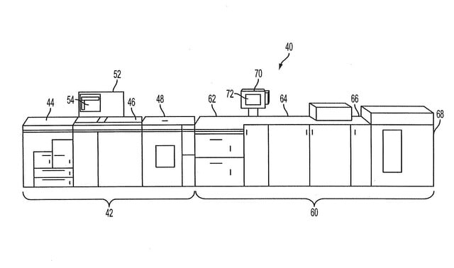
[0022] A second print line indicated generally at 60 
【0019】
  第2プリントラインは包括して60で示し、

is juxtaposed to the finisher 48 of print line 42 ;
プリントライン42のフィニッシャ48に並んで設けられ、すなわち並設され

and, the print line 60 includes a feeder 62 , a multi-colorant marking engine 64 , a merge and transport unit 66 and a finishing unit 68 .
プリントライン60は給紙装置62、多色カラーマーキングエンジン64、合流移送ユニット66、及び仕上げユニットであるフィニッシングユニットであるフィニッシャ68を備える。

A controller 70 is provided with a graphical user interface 72 provided thereon;
コントローラ70はその上部にグラフィカルユーザインタフェース72を備えて設けられ、

and, the controller 70 may include the digital front end (DFE) for the marking engine 66 .
コントローラ70はマーキングエンジン64のためのデジタルフロントエンド(DFE)を備えてもよい。

コメント
  • X
  • Facebookでシェアする
  • はてなブックマークに追加する
  • LINEでシェアする

中2数学 連立方程式あと少しで終わり

2021-07-16 00:14:39 | 電験3種チャレンジ

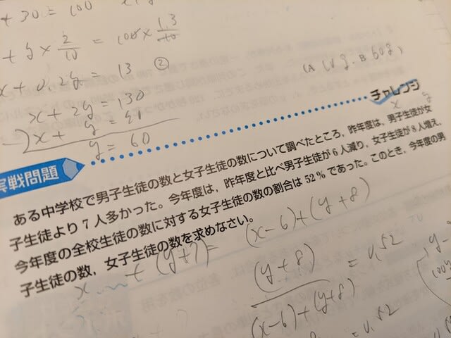
遅々として進んではいる中学数学の復習。参考書(チャート式)、あと応用編数ページでようやく連立方程式が終了します。

悩みまくって解答参照。今年度の人数を基準にしないといけない、でないと今年度の女子生徒の割合52%を使ってシンプルな式を作れない。

コメント
  • X
  • Facebookでシェアする
  • はてなブックマークに追加する
  • LINEでシェアする

傾き

2021-07-15 19:41:46 | 英語特許散策

WO2019140244
[0148] In other cases, the ranges of input values may be such that part of the range can be divided into segments or partitions of equal length, but one part or two parts of the range have a slope such that these parts cannot have the same length at the other ranges.
【0160】
  [0148]他の場合には、入力値のレンジは、レンジの一部が、等しい長さのセグメントまたはパーティションに分割され得るが、そのレンジの1つの部分または2つの部分は、これらの部分が、他のレンジにおいて同じ長さを有することができないような傾き(slope)を有する。

FIG. 9 includes a graph that plots a y-value for a range of input values of x, according to a piecewise linear function for dynamic range adjustment.
図9は、ダイナミックレンジ調整のための区分線形関数に従って、xの入力値のレンジについてy値をプロットするグラフを含む。

The x values can be luma values from pixels in a video frame, for example.
x値は、たとえば、ビデオフレーム中のピクセルからのルーマ値であり得る。

In this example, the range of x values includes five ranges, R0, Rl, R2, R3, and R4, that each have an approximately constant slope.
この例では、x値のレンジは、各々ほぼ一定の傾きを有する5つのレンジ、R0、R1、R2、R3、およびR4を含む。

As illustrated in this example, four of the ranges, Rl, R2, R3, and R4 are of the same length, while one range, R0, has a different length.
この例に示されているように、レンジのうちの4つ、R1、R2、R3、およびR4は、同じ長さのものであるが、1つのレンジ、R0は、異なる長さを有する。

US10260858
For each opening, the average of open and close pulse widths corresponds to a point midway between open and close values, shown as points along curve 1403, the curve connecting the average points is the average curve 1403.
【0075】
  各開口について、開放及び閉鎖パルス幅の平均は、曲線1403に沿った点として示された開放及び閉鎖値の間の中間点に対応し、平均点を結ぶ曲線は、平均曲線1403である。

Each average point on curve 1403 is (close time+open time)/2.
曲線1403上の各平均点は、(閉鎖時間+開放時間)/2である。

Thus, twice the average value is the sum of (close time+open time), which should be roughly constant if the velocity is constant.
それゆえに、平均値の2倍は、速度が一定であればほぼ一定でなければならない(閉鎖時間+開放時間)の合計である。

Hence the average curve 1403 for an object that travels at a constant velocity through the channel should look like a horizontally flat line).
したがって、流路を介して一定速度で移動する物体についての平均曲線1403は、水平方向に平坦な線のようにみえるべきである。

In FIG. 14, the average curve 1403 is increasing over time, with a positive slope, which is an indication that the object is slowing as it travels across the spatial filter.
図14において、平均曲線1403は、空間フィルタを横切って移動するときに物体が減速しているという指示である正の傾きを有して時間の経過とともに増加している。

The sloping average curve 1403 is the result of the situation that arises when the object takes successively more time to cross subsequent mask openings, on average.
傾きの平均曲線1403は、平均において後続のマスク開口を横断するために物体が連続的により多くの時間がかかるときに生じる状況の結果である。

The slope of the average curve 1403 can therefore be used to tell whether the object is actually slowing or accelerating as it travels through the channel.
したがって、平均曲線1403の傾きは、流路を通って移動するときに物体が実際に減速又は加速しているかどうかを見分けるために使用されることができる。

In addition to the average object velocity information obtained from either the time or frequency domain signals, the spatial filter
時間又は周波数領域信号のいずれかから得られた平均物体速度情報に加えて、空間フィルタは、

can be used to provide information about the instantaneous velocity of an object as it travels along the flow path, including whether the object is accelerating or slowing down, and by what amount, on a mask feature-by-feature basis.
マスク特徴ベースにおいて、物体が加速又は減速しているかどうかを含む及び合計のものにより流路に沿って移動するときの物体の瞬間速度に関する情報を提供するために使用されることができる。

コメント
  • X
  • Facebookでシェアする
  • はてなブックマークに追加する
  • LINEでシェアする

コンクリート型枠

2021-07-15 19:39:13 | 英語特許散策

WO2019112555
[00115] In certain embodiments, the concrete mold used to produce a set of discrete objects
【0094】
  特定の実施形態では、一連の別個の物体を製造するために使用されるコンクリート型枠は、

is modified to change the spacing between the plurality of the discrete objects according the chambers flow distribution profile and improve the carbon dioxide and water diffusion rates across the channel forming object faces.
チャンバーのフロー分布プロファイルに従って複数の別個の物体間の間隔を変更し、チャネルを形成する別個の物体の面にわたって二酸化炭素および水の拡散速度を改善するように変更される。

WO2019070309
C. Concrete Forms.
【0029】
C.コンクリート型枠

As shown throughout the figures, the concrete forming system 10 may include a first wall 30 and a second wall 40 in a spaced-apart, opposed relationship with respect to the first wall 30.
図面を通じて示されるように、コンクリート成形システム10は、第1壁30と、第1壁30に対して離間して対向する関係にある第2壁40とを含んでもよい。
 
Such a configuration creates a concrete form having a cavity 62 in which concrete 12 may be poured and allowed to cure to form a structure 16.
このような構成は、構造16を成形するために、コンクリート12を打設し、硬化させることを可能にしてもよい空洞62を有するコンクリート型枠を作成する。
 
WO2017025796
[0004] For purposes of end-to-end interconnection, the panels generally include vertically extending end walls having a series of spaced openings therethrough.
【0004】
  この端部同士を相互連結するために、これらのパネルは、一連の相互離間された貫通開口を有する垂直方向に延在する端壁部を一般的に備える。
 
When aligned in juxtaposition, the individual panels are typically interconnected, such as by means of slotted pin and wedge assemblies.
並置状態に配列されると、個々のパネル同士は、典型的にはスロット付きピンおよびウェッジアセンブリなどにより相互連結される。
 
When the form is disassembled, the wedges are loosened and removed, and the pins extracted from the form panel apertures.
型枠が分解されるときには、これらのウェッジは緩められ除去され、ピンは型枠パネルアパーチャから抜かれる。
 
WO2013119448
The form system includes a bottom form panel member 63 that is movable along the height of the form portion 64
型枠システムは、底部型枠パネル部材63を含み、この底部型枠パネル部材63は、型枠部分64の高さに沿って動くことができ、
 
and can be bolted in place using bolt holes 69 provided in the form structure 64. 
そして型枠構造体64に設けられたボルト穴69を用いて定位置にボルト止めできる。
コメント
  • X
  • Facebookでシェアする
  • はてなブックマークに追加する
  • LINEでシェアする

オンオフを制御

2021-07-15 19:05:36 | 英語特許散策

US9134547
[0337] Some embodiments provide for eyewear 700 having electrochromic functionality incorporated into the laminate 710 .
【0251】
  いくつかの実施形態は、積層体710に機能的に組み込まれたエレクトロクロミックを有する眼鏡700を提供する。

The eyewear 700 can include a power source, such as a battery, an electrical contact, and a conductor that conveys a voltage to an electrode in the electrochromic laminate.
眼鏡700は、バッテリ等の電源と、電気コンタクトと、エレクトロクロミック積層体の電極に電圧を供給する導体と、を含むことができる。

The eyewear 700 can include a user interface element integrated into the frame 704 , the earstems 706 , the lens 702 , or any combination of these.
眼鏡700は、フレーム704、テンプル706、レンズ702またはこれらのいずれかの組み合わせに内蔵されたユーザインタフェース要素を含むことができる。

The user interface element can be configured to allow the user to control activation and deactivation of the electrochromic layer.
ユーザインタフェース要素は、使用者がエレクトロクロミック層の作動のオンオフを制御できるように構成することができる。

WO2019079646
During second transition 340B, transistor switch M3 (e.g., first transistor switch) is turning on and transistor switch Ml (e.g., second transistor switch) is turning off.
第2の遷移340Bの間、トランジスタスイッチM3(例えば、第1トランジスタスイッチ)がターンオンしつつあり、トランジスタスイッチM1(例えば、第2トランジスタスイッチ)がターンオフしつつある。

Second PWM control signal 202 controls turning on and turning off of transistor switch Ml and shielding switch 224.
第2PWM制御信号202は、トランジスタM1とシールディングスイッチ224のオンオフを制御する。

Fourth PWM control signal 202 controls turning on and turning off of transistor switch M2 and shielding switch 224B.
第4PWM制御信号202は、トランジスタM2とシールディングスイッチ224Bのオンオフを制御する。

US8893677
[0034] The piloted valve may be controlled on/off with the same hydraulic circuit that engages or releases one of the two lock pins.
【0011】
  パイロット弁は、2つのロックピンの一方と係合するまたはそれを解除する同じ液圧回路でオン/オフを制御可能である。

This shortens the variable cam timing (VCT) control valve to two hydraulic circuits, a VCT control circuit and a combined lock pin/hydraulic detent control circuit.
これは可変カムタイミング(VCT)制御弁を2つの液圧回路、すなわちVCT制御回路と組合せ型ロックピン/液圧デテント制御回路とに縮める。

Movement of the piloted valve to the first position is actively controlled by the remote on/off valve or the control valve of the phaser.
パイロット弁の第1位置への移動は、位相器の遠隔オン/オフ弁または制御弁によって能動的に制御される。

US10462437
[0058] In this embodiment, the highlight projector comprises
【0042】
  この実施例では、ハイライトプロジェクタは、

a high-intensity narrow beam light source 34 that can be controlled to emit a narrow beam of light 35 that is steered by a X-Y deflector 36 
X-Y偏向器36によって誘導される細い光線35を出すように制御され得る高強度狭ビーム光源34と、

and optical combiner 37 to produce a brightly illuminated spot 38 on spatial light modulator 32 .
空間光変調器32で明るく照らされるスポット38を創出する光学コンバイナ37とを含む。

By controlling the intensity and/or turning on or off light source 34 while scanning with X-Y scanner 36 ,
X-Yスキャナ36で走査しながら光源34の強度及び/又はオン・オフを制御することによって、

a plurality of different highlight areas may be illuminated on spatial light modulator 32 with light from light source 34 
複数の異なるハイライト領域は、光源34からの光を用いて空間光変調器32上で照らされ得る。

US9881772
[0085] System controller 702 also interfaces with power controllers 710 712 , and 714 ,
【0079】
  システムコントローラ702は、電力コントローラ710、712、および714とも相互作用する。

which regulate whether the corresponding RF powers 720 722 , and 724 are turned on or off, and if a power is turned on, to what power setting. In one embodiment, the frequency of RF power source 120 is 400 kHz.
電力コントローラは、対応するRF電源720、722、および724のオンオフを制御し、電源がオンになった際に電力設定値へ制御する。

コメント
  • X
  • Facebookでシェアする
  • はてなブックマークに追加する
  • LINEでシェアする

起立

2021-07-15 16:56:28 | 英語特許散策

WO2019227119
[0027]
Next, an air curtain guide 100 of the present embodiment will be described using Figure 2.
【0026】
  次に、図2を用いて、本実施形態のエアカーテンガイド100について説明する。

As shown in Figure 2, the air curtain guide 100 is attached to the front end of the shelf board 23.
図2に示すように、エアカーテンガイド100は、棚板23の前端に取り付けられる。

The air curtain guide 100 has an insertion part 30, an extending part 40, a rising part 50, and a guide part 60.
エアカーテンガイド100は、挿入部30と、延出部40と、起立部50と、ガイド部60とを有する。

EP3564020
[0024] Figure 3B illustrates an example wherein the tool uses the plasticity of the material (314) to pull the material (314) in a vertical direction to form thin upright strands or pillars (308).
【0038】
  図3Bは、ツールが、材料(314)の可塑性を利用して垂直方向に当該材料(314)を引いて、細い起立ストランド(strands)又はピラー(308)を形成する例を示す。

Thus, the deposited material (314) is drawn from an anchor (316)
同図において、付着された材料(314)は、アンカー(316)から引かれて、

and forms a pillar (308) including a base (318) (e.g., extrusion base) and an upright (320) (e.g., extrusion),
基部(318)(例えば、押出基部)及び起立部(320)(例えば、突出部)を含むピラー(308)を形成しており、

the upright (320) having an average diameter Daverage along the upright (320) or extrusion and an angle θ with respect to a vertical direction (322).
当該起立部(320)は、起立部(320)又は突出部に沿って平均直径Daverageを有するとともに、垂直方向(322)に対して角度θを有する。

In one example, material (314) is also fed or deposited during the pulling to form the pillar (308).
一例においては、材料(314)は、ピラー(308)を形成するための引出作業中にも供給される。

The process conditions during deposition or pulling of the material (314) may be controlled to obtain various shapes for the pillar (308).
様々な形状の材料(314)を得るために、材料(314)の付着作業中又は引出作業中の処理条件を調節することができる。

In one or more examples, the base (318) on the anchor (316) is thicker than the upright (320) portion of the pillar (308).
1つ以上の例においては、アンカー(316)における基部(318)は、ピラー(308)の起立部(320)よりも太い。

WO2018200285
[0057] After anvil (400) is secured to trocar (330), the operator then rotates knob (130) to cause trocar (330) and anvil (400) to retract proximally as described above.
【0031】
  アンビル(400)がトロカール(330)に固定された後、操作者は次いで、上述のように、ノブ(130)を回転させてトロカール(330)及びアンビル(400)を近位側に後退させる。

When trocar (330) and anvil (400) are properly secured to one another,
図13A~図13Eを参照して後述するように、トロカール(330)及びアンビル(400)が互いに適切に固定されている場合、

this proximal retraction of trocar (330) and anvil (400)
トロカール(330)及びアンビル(400)のこの近位後退が、

compresses the tissue of tubular anatomical structures (20, 40) between surfaces (412, 322) of anvil (400) and stapling head assembly (300) as described below with reference to FIGS. 13A-13E.
アンビル(400)とステープル留めヘッドアセンブリ(300)との表面(412、322)の間で管状解剖学的構造(20、40)の組織を圧縮する。

When trocar (330) and anvil (400) are not properly secured to one another, trocar (330) is retracted proximally without anvil (400), such that the tissue of tubular anatomical structures (20, 40) remains uncompressed.
トロカール(330)及びアンビル(400)が互いに適切に固定されていない場合、トロカール(330)はアンビル(400)なしに近位側に後退し、管状解剖学的構造(20、40)の組織は圧縮されないままとなる。

When trocar (330) and anvil (400) are properly secured to one another, as trocar (330) and anvil (400) are retracted proximally,
トロカール(330)及びアンビル(400)が互いに適切に固定されている場合、トロカール(330)及びアンビル(400)が近位側に後退すると、

a proximal end of shank (420) of anvil (400) engages a raised portion (604) of flange (612) of actuator spring (602)
アンビル(400)のシャンク(420)の近位端が、アクチュエータバネ(602)のフランジ(612)の起立部(604)と係合して、

and thereby drives flange (612) toward flange (614), thereby actuating dome switch (610) as shown in FIGS. 9B and 10B. 
フランジ(612)をフランジ(614)に向けて駆動し、それにより、図9B及び図10Bに示すようにドームスイッチ(610)が作動される。

コメント
  • X
  • Facebookでシェアする
  • はてなブックマークに追加する
  • LINEでシェアする

当ブログの例文について

本ブログの「特許英語散策」等題した部分では、英語の例文を管理人の独断と偏見で収集し、適宜訳文・訳語を記載しています。 訳文等は原則として対応日本語公報をそのまま写したものです。私個人のコメント部分は(大抵)”*”を付しています。 訳語は多数の翻訳者の長年の努力の結晶ですが、誤訳、転記ミスもあると思いますのでご注意ください。