


US2011148049
"[0025] As indicated above, to facilitate attachment and retention of the gasket assembly 10 to the one of the members (not shown) being clamped together, the elastomeric portion 32 is formed about the projection 28, such as in a molding process, wherein the projection 28 is completely or substantially encapsulated within the elastomeric portion 32. As best shown in FIG. 5, the elastomeric portion 32 extends and transitions smoothly from the projection wall 29 into a flush or substantially flush relation with the upper surface 20 of the carrier body 12. The elastomeric portion 32 is configured, in its “as molded” configuration, to be retained within a predetermined size pocket of one of the members being clamped together. In addition, to further facilitate retention, the elastomeric portion 32 preferably has an annular bulbous region 34 that is sized for a line-to-line or slight interference fit within the pocket of the member. The bulbous region 34 is shown extending radially outwardly between an upper, radially inwardly tapered region 35 and a lower radially inwardly extending valley 37. As such, during assembly, the tapered region 35 facilitate initial entry of the feature 18 into the respective pocket of the member, while the valley 37 allows the elastomer material to flow axially as needed during interference of the bulbous region 34 with the wall of the pocket or receptacle. In addition, to facilitate assembly, the bulbous region 34 is formed having at least one, and shown as a plurality of scallops (three equally spaced scallops), also referred to as recessed sectors 41 to allow air to readily evacuate the respective pocket or receptacle upon being disposed therein. If not for the recessed sectors 41, a pressure build up of compressed air between the bulbous region 34 and the pocket could prevent the gasket from being properly positioned during assembly. "
上で示したように、ともにクランプされる部材(図示せず)の1つにガスケットアセンブリ10を取り付けおよび保持することを促進するよう、エラストマー部分32がたとえば成型処理において突出部28の周りに形成される。突出部28は、完全または実質的にエラストマー部分32内に封入される。図5にもっともよく示されるように、エラストマー部分32は、担体本体12の上部表面20と面一または実質的に面一の関係になるように突出壁29からスムーズに延在および遷移する。エラストマー部分32は、その「成型された状態」の構成において、ともにクランプされる部材同士の1つのうちの所定サイズのポケット内に保持されるよう構成される。さらに保持を促進するために、エラストマー部分32は好ましくは、環状の球状領域34を有する。環状の球状領域34は、上記部材のポケット内において線対称嵌合または若干の締まり嵌めのためにサイズ決めされる。球状領域34は、半径方向内方に先細りになる上部領域35と、半径方向内方へ延在する下部谷部37との間において、半径方向外方に延在するよう示される。したがって、組み付けの間、先細りになる領域35が部材のそれぞれのポケットへの機構18の初期の導入を促進する一方、谷部37が、ポケットまたはレセプタクルの壁との球状領域34の干渉の間に必要とされるように軸方向にエラストマー材料を流すことを可能にする。さらに、組み付けを促進するよう、球状領域34は、窪んだ区域41とも称される少なくとも1つ、示されるのは複数のスカラップ(3つの等しく間隔を置いて配置されるスカラップ)を有するよう形成される。これにより、配置される際に、それぞれのポケットまたはレセプタクルから容易に空気を排気することが可能になる。窪んだ区域41が設けられなかった場合、球状領域34とポケットとの間の圧縮空気の圧力増大により、組み付けの間にガスケットが適切に位置決めされることが妨げられ得る。
"[0026] In manufacture, the carrier body 12, having had the through opening 26 and projection 28 already formed therein, is disposed in a mold cavity with a mold injection sprue or sprues of the mold machine extending upwardly in generally coaxial alignment with a central axis 36 of each of the through openings 26. Additional injection sprues can be incorporated as desired to provide the needed flow of elastomeric material. For example, the gasket body 12 can be formed having additional injection points, such as shown by recesses 43 in the inner portion 17, for example. The mold cavity is formed having the desired negative shape of the elastomeric portion 32 to be formed about the projection 28. As the melted elastomeric material is injected through the through openings 26, it is caused to flow through the channel 30, whereupon it flows through the annular gap 23 to form the seal bead 14 located between the inner portion 17 and the outer portion 19 and about the outer periphery 45 of the inner portion 17 to form in part the seal bead 14 about the inlet opening 16, which is also formed in part by elastomeric material bonded to the inner periphery 33 of the outer portion 19. Accordingly, upon completing the molding process, the elastomeric portions 32 and the seal bead 14 are connected as a continuous, monolithic piece of the elastomeric material via a bridge 39 of the elastomeric material. It should be recognized that the sealing bead 14 can be formed having any suitable geometry, depending on the application. Desirably, the sealing bead 14 has a portion extending outwardly beyond the opposite surfaces 20, 22 (above the upper surface 20 and below the lower surface 22), such that upon clamping the members into abutment with the carrier body 12, the sealing bead 14 is caused to elastically deform into sealed abutment with sealing surfaces of the members being clamped together. "
製造において、貫通開口部26および突出部28がすでに形成された担体本体12は、成型機械の射出成型スプルーが、貫通開口部26の各々の中心軸36と略共軸に整列して上方向に延在する状態で、成型キャビティ内に配置される。付加的な射出スプルーが所望のように統合され得、これによりエラストマー材料の必要とされる流れを提供する。たとえば、内側部分17における窪み43によって、ガスケット本体12は付加的な注入ポイントを有するよう形成され得る。成型キャビティは、突出部28の周りに形成されるエラストマー部分32の所望の窪み形状を有するよう形成される。溶けたエラストマー材料が、貫通開口部26を通って注入されると、チャネル30を通って流れる。その際、環状ギャップ23を通って流れ、内側部分17と外側部分19との間であって、内側部分17の外周縁45の周りに配置される封止ビード14を形成する。これにより、外側部分19の内周縁33に接合されるエラストマー材料によって部分的に形成されるインレット開口部16の周りに部分的に封止ビード14を形成する。これにより、成型処理を完了すると、エラストマー部分32および封止ビード14は、エラストマー材料の連続的なモノリシックピースとして、エラストマー材料のブリッジ39を介して接続される。なお、封止ビード14は、用途に依存して任意の好適な形状を有するよう形成され得る。望ましくは、部材をクランプして担体本体12と当接させる際に、封止ビード14は弾性変形されて、ともにクランプされる部材同士の封止面と封止当接するように、対向する表面20,22を超えて外方向に(上部表面20の上および下部表面22の下)延在する部分を有する。
US2016160872
"[0011] Embodiments relate to a sealing system between the backface of the compressor impeller and neighboring components, such as the bearing housing and/or the insert. The sealing system can improve the seal between the dynamic rotating assembly components and the complementary static components on the compressor-end of a turbocharger, thereby minimizing compressor-end oil passage and blow by. As used herein, the term “blow by” refers to high pressure change air (on compressor side) or exhaust gas (on turbine side) leaking into bearing housing and into engine crankcase. The sealing system can include sealing elements such as an external purge gas to enhance a clearance seal. The sealing elements can be operatively positioned at an interface between the rotating assembly and the complimentary static components. The purge seal selectively provides external pressurized gas or internally supplied charge gas (i.e., air) to the interface at the clearance seal to maintain an inward directed pressure gradient regardless of turbocharger operating conditions. The purge seal is supplied with gas via a gas supply path that includes a gas passageway formed in the bearing housing, one or more radial bores formed in an insert of the rotating assembly, and an axisymmetric cavity formed in the bearing housing intermediate to, and in fluid communication with, the gas supply path and the insert's radial bores. The axisymmetric cavity serves as an annular manifold to deliver gas to the insert radial bores, regardless of the orientation of the insert within the bearing housing. It is understood, however, that adding purge gas does not reduce blow-by leakage below the clearance seal's normal capability to prevent blow-by leakage. "
実施例は、圧縮機インペラの背面と軸受ハウジング及び/又は挿入部のような隣接している構成要素間の封止システムに関する。封止システムは、ターボ過給機の圧縮機端部上の動的回転組立体構成要素と相補型の固定構成要素との間の封止を改善することによって、圧縮機端部のオイル通過及びブローバイを最小化することができる。本明細書に用いられる用語「ブローバイ」は、高圧充填空気(圧縮機側)又は排気ガス(タービン側)の軸受ハウジング内への、及びエンジンクランクケース内への漏出を意味する。封止システムは、隙間シールを改善するために、外部パージガスシールのような封止要素を含むことができる。封止要素は、回転組立体と相補型の固定構成要素との間の界面に作動可能に配置することができる。パージシールは、ターボ過給機の作動条件に関わらず、内向圧力勾配を保持するために、隙間シールから界面に外部加圧ガス又は内部供給充填ガス(すなわち、空気)を選択的に提供する。パージシールには、軸受ハウジングに形成されたガス通路、回転組立体の挿入部に形成された1つ以上の半径方向ボア、及びガス供給通路と挿入部の半径方向ボアの中間に位置し、これらと流体連通する軸受ハウジングに形成された線対称キャビティを含むガス供給経路を通じてガスが供給される。線対称キャビティは、軸受ハウジングの内部における挿入部の方位に関係なく、挿入部の半径方向ボアにガスを送るための環状マニホールドとしての役割を果たす。しかしながら、パージガスの追加がブローバイ漏出を防止するための隙間シールの正常の能力を超えてブローバイ漏出を減少させないことを理解すべきである。
EP2984733
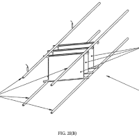
"Fig. 27 shows an axi-symmetric view of a variation based on the system shown in Fig. 26 . Only one surface of the lossy material is covered by a layered structure of copper and magnetic materials. The inductor loop is placed on the side of the copper and magnetic material structure opposite to the lossy material as shown."
【図27】図26に示すシステムに基づくバリエーションの線対称図であり、損失性材料の片面だけを銅及び磁性材料の層状構体によってカバーする。インダクタループは、銅及び磁性材料の構体における損失性材料とは反対側に位置する。
EP2785299
"[0040] The staple fiber web, such as when utilized as a fluid transport element of an assembled intermediate, can have various shapes including symmetrical (having a point, line, or plane of symmetry) or unsymmetrical shapes. The shape of the webs is envisioned to include but are not limited to circles, ovals, squares, rectangles, pentagons, hexagons, octagons, trapezoids, truncated pyramids, hourglasses, dumbbells, dog bones, etc. The edges and corners can be straight or rounded. The sides can be curved (convex or concave), tapered, flared, or angled. In addition, the web can contain cut-out regions that create voids, cavities, depressions, channels, or grooves. In some embodiments, the shape of the web is preferably rectangular. Regardless of the shape, the staple fiber web fluid transport elements can generally be defined as having a first major face, a second opposing major face substantially parallel to the first major face, and a thickness in a direction orthogonal to the first and second major face. "
複合中間材の流体移送要素として使用する際等の短繊維ウェブは、対称(点対称、線対称、又は面対称)形状又は非対称形状を含む種々の形状であり得る。ウェブの形状は、円、卵形、正方形、矩形、五角形、六角形、八角形、台形、角錐台、砂時計、ダンベル、犬用の骨等を含むと思われるが、これらに限定されるものではない。縁部と角部は真っ直ぐでも丸みがあってもよい。側面は曲がっていても(凸又は凹)、先細、フレア、又は角があってもよい。また、ウェブは、空隙、空洞、凹部、通路、又は溝を作る切欠き部を含み得る。一部実施形態において、ウェブの形状は矩形であることが好ましい。形状に関わらず、短繊維ウェブ流体移送要素は、一般に、第1主面と、第1主面に対してほぼ平行な第2対向主面と、第1主面及び第2主面に直行する方向の厚みと、を有すると画定される。


※コメント投稿者のブログIDはブログ作成者のみに通知されます