


US5359813
"Carriage traverse assembly 30 includes motor 32, coupling 34, and lead screw mechanism 36. Coupling 34 enables the motor to deliver rotational force to the lead screw mechanism 36, despite shaft misalignments, and the lead screw mechanism translates such force into linear motion which moves carriage 38 along base 28 in the direction of arrows A and B. Swivel table 40 is secured atop carriage 38, and moves in concert with the carriage. A cover 42 is secured to one side of carriage 38, and extends laterally to prevent debris from entering the narrow gap defined between carriage 38 and base 28; bearings and lubricating fluid fit within the narrow gap (not visible in FIG. 1) to insure smooth, and precise, movement of carriage 38. A second cover is secured to the opposite end of the carriage.
Tailstock 44 is secured to swivel table 40 by a dovetail connection; tailstock 44 is movable laterally along swivel table 40, as indicated by the directional arrows A and B."
「このキャリッジ横断組立体30は、モータ30と、継ぎ手34と、リードスクリュウ機構36を含む。継ぎ手34は、たとえ軸ズレがあってもモータの回転駆動力がリードスクリュウ機構36に伝達可能にでき、またリードスクリュウ機構36はこのような駆動力を直線運動に変換して、キャリッジ38を矢印AとB方向にベース28に沿うように移動する。スイベルテーブル40は、キャリッジ38の上に固定されており、キャリッジと協動して移動する。カバー42はキャリッジ38の側面に固定されて横方向に延設されており、キャリッジ38とベース28の間で規定される狭い隙間から研磨紛が内部に侵入することを防止して、(図1では見る事ができない)隙間と軸受けの間に潤滑液が浸透して、円滑で正確なキャリッジ38の移動を保証する。このキャリッジの反対側には第2のカバーが固定される。
テイルストック44はスイベルテーブル40に対してアリ溝結合され、このテイルストク44はスイベルテーブル40に沿うように横方向の矢印AとB方向に移動可能にされる。」
WO2015040617
"1. A trocar adapted for insertion through a fascia layer of an abdominal wall, comprising:
a proximal end configured for handling by a user;
a distal end configured for insertion into tissue; and
a shaft extending in between said proximal end and distal end;
wherein said shaft comprises a narrow portion proximal to said distal end, said narrow portion defining at least one recess shaped and sized to receive fascia tissue, said recess ending, at a distal end of said recess, with a generally proximally facing surface of said shaft configured directly below said narrow portion, said proximally facing surface and said narrow portion shaped and sized to stabilize said trocar in the abdominal wall by the fascia."
"37. The kit according to claim 36, wherein said recess is trapezoidal and defines a dovetail coupling between said anchor and said cannula."
「1. 腹壁の筋膜層を通る挿入のために適合されたトロカールであって、
使用者による取り扱いのために構成された近位端と、
組織への挿入のために構成された遠位端と、
前記近位端と前記遠位端との間に延びるシャフトと
を備え、
ここにおいて、前記シャフトは、前記遠位端の近位に狭窄部分を備え、前記狭窄部分は、筋膜組織を受け入れるような形状および大きさにされた少なくとも1つの凹部を画定し、前記凹部は前記凹部の遠位端で終わり、前記シャフトの全体的に近位に向いた表面は前記狭窄部分の真下に構成され、前記近位に向いた表面および前記狭窄部分は、前記筋膜によって前記腹壁内で前記トロカールを安定させるような形状および大きさとされる、トロカール。」
「37. 前記凹部は台形であり、前記アンカーと前記カニューレとの間で結合するアリ溝を画定する、請求項36に記載のキット。」
US9587745(JP)
"The cross-sectional shape of the buffer groove 11 may be, for example, in a semicircular shape as shown in FIG. 2B, a rectangular shape as shown in FIG. 2C, or a dovetail groove shape as shown in FIG. 2D, but is not limited thereto."
「[0029] また、緩衝溝11の断面形状は、特に限定されないが、例えば、図2(b)に示すような半円状、同(c)に示すような矩形、同(d)に示すようなアリ溝状に形成される。」
WO2011128385
(Ab)
"A method and apparatus are disclosed which are suitable for use in the manufacture of two-piece metal containers. In particular, a press is disclosed which makes cup sections from metal sheet using a combination of drawing and stretching operations. The cups resulting from the press have the advantage of having a base thickness that is thinner relative to the ingoing gauge of the metal sheet."
「本発明は、ツーピース金属容器の製造での使用に適する方法及び装置を提供する。特に、絞り加工及び延伸加工工程の組み合わせを用いて、金属シートからカップセクションを作るプレス機が開示される。プレス機から得られるカップには、金属シートの到来標準寸法と比較して薄い基部を備えるという利点がある。」
WO2009154653
(Ab)
"Metal discs, preferably circular, are cut to a precise diameter and drawn to a preform with a channel and skirt for an aerosol valve mounting cup. The preform then undergoes further forming operations at the stations in a press system. 'Bumping' is carried out on the skirt edge at a station, to eliminate non- burr trimming of the cup edge, save material and obtain a carefully controlled skirt height and a substantially even skirt edge with minimized earring. The resultant cup terminating skirt edge is characterized by reformed metal. A further coaxing or pinch-cut operation may be performed on the cup skirt."
「好ましくは円形である金属ディスクが、正確な直径に切断され、エアロゾルバルブの装着カップのチャネルとスカートとを備えたプリフォームに絞り加工される。そして、このプリフォームは、プレス加工システムのステーションでさらなる形成動作を受ける。カップの縁のトリミングの必要性をなくし、材料を節約し、注意深く制御されたスカート高さと、イヤリングが最小のほぼ平坦なスカートの縁を得るために、所定のステーションでスカートの縁に「バンピング」が行われる。製造されたカップのスカートの終端縁は、変形された金属により特徴付けられる。さらなるコーキシング又はピンチカット動作が、このカップのスカートに行われることができる。」
「愛国心はならず者の最後の拠り所」
"Patriotism is the last refuge of the scoundrel." (Political views of Samuel Johnson, Wikipedia)
WO2010059568
"1. A combination, comprising: a multilayer optical film having a plurality of microlayers arranged into optical repeat units for reflecting light over an extended wavelength band, adjacent microlayers having refractive index differences that define a first and second in-plane axis(*なぜ単数?同一名称複数部材の修飾、冠詞、初出), such that the film has a reflectivity of at least 75% for all polarization states of normally incident light, the refractive index differences also being such that for p-polarized light incident on the film in a first plane of incidence that includes the first axis, the film has a reflectivity that decreases by at least half from an initial value at normal incidence to a value Rl at an incidence angle θoblique, but for p-polarized light incident on the film in a second plane that includes the second axis, the film has a reflectivity R2 > Rl at the incidence angle θoblique; and a polarizer having a pass axis and a block axis, the polarizer and the multilayer optical film being disposed to define an oblique transmission lobe; wherein the optical repeat units have an optical thickness distribution across a thickness of the multilayer optical film, the thickness distribution defining a thin side and a thick side of the multilayer optical film, thinner ones of the optical repeat units being disposed generally towards the thin side and thicker ones of the optical repeat units being disposed generally towards the thick side; and wherein the thin and thick sides of the multilayer optical films are oriented relative to the polarizer to enhance an azimuthal collimation Δφe of the transmission lobe."
「 拡張された波長帯域にわたって光を反射するために光学的反復単位で配置された複数のマイクロ層を有する多層光学フィルムであって、隣接するマイクロ層は、前記フィルムが全ての偏光状態の垂直入射光において少なくとも75%の反射率を有するように、第1面内軸及び第2面内軸を画定する屈折率差を有し、該屈折率差はまた、前記第1面内軸を含む第1入射面にて前記フィルムに入射するp偏光に関し、前記フィルムが垂直入射における初期値から斜角θの入射における値R1まで、少なくとも半減する反射率を有し、前記第2面内軸を含む第2面にてフィルムに入射するp偏光に関し、前記フィルムが斜角θの入射におけるR1よりも大きいR2の反射率を有するように構成される、多層光学フィルムと、
透過軸及び遮蔽軸を有する偏光子であって、該偏光子及び前記多層光学フィルムが斜めの透過ローブを画定するように配される、偏光子と、を含む、組み合わせ体であって、
前記光学的反復単位が前記多層光学フィルムの厚さ方向に光学的厚さ分布を有し、前記光学的厚さ分布は前記多層光学フィルムの薄い側及び厚い側を画定し、前記光学的反復単位のより薄いものが概して前記薄い側に向けて配され、前記光学的反復単位のより厚いものが概して前記厚い側に向けて配され、
前記多層光学フィルムの前記薄い側及び前記厚い側が、前記透過ローブの方位コリメーションΔφeを向上させるように前記偏光子に対して方向付けられる、組み合わせ体」
US5612908
(Ab)
"Image processing for multimedia workstations is a computationally intensive task requiring special purpose hardware to meet the high speed requirements associated with the task. One type of specialized hardware that meets the computation high speed requirements is the mesh connected computer. Such a computer becomes a massively parallel machine when an array of computers interconnected by a network are replicated in a machine. The nearest neighbor mesh computer consists of an NxN square array of Processor Elements(PEs) where each PE is connected to the North, South, East and West PEs only. Assuming a single wire interface between PEs, there are a total of 2N2 wires in the mesh structure. Under the assumtion of SIMD operation with uni-directional message and data transfers between the processing elements in the meah, for example all PES transferring data North, it is possible to reconfigure the array by placing the symmetric processing elements together and sharing the north-south wires with the east-west wires, thereby reducing the wiring complexity in half, i.e. N2 without affecting performance. The resulting diagonal folded mesh array processor, which is called Oracle, allows the matrix transformation operation to be accomplished in one cycle by simple interchange of the data elements in the dual symmetric processor elements. The use of Oracle for a parallel 2-D convolution mechanish for image processing and multimedia applications and for a finite difference method of solving differential equations is presented, concentrating on the computational aspects of the algorithm."
「最近隣メッシュ・コンピュータはNxN方形アレイのプロセッサ要素(PE)からなり、各PEが東西南北のPEのみに接続されている。PEの間に単線のインタフェースを想定した場合、メッシュ構造内には合計2N2本のワイヤが存在する。たとえば、すべてのPEが北へデータの転送を行うSIMD操作を想定した場合、対称的な処理要素を重ね合わせ、北-南のワイヤと東-西のワイヤを共用し、これによって、配線をN2本に半減することによって、アレイを再構成することが可能である。これによって、マトリックス変形操作を2重対称処理要素内のデータ要素を交換するだけで1サイクルで行えるようになる。」
WO2015195531
"These CD8+ T cells were then cultured in the presence of immobilized anti-CD3 antibody, a treatment known to stimulate polyclonal T cell activation, and treated stimulated cultures with soluble versions of either synTac IGRP-PD-L1 or synTac TUM-PD- Ll to examine the antigen specificity of any suppressive effect. A version of synTac IGRP without PD-L1 served as an effector control for the MOD domain. Before seeding, cells were labeled with carboxyfluorescein succinimidyl ester (CFSE), a fluorescent cytosolic dye whose intensity halves with each cell division, in order to monitor the extent of T cell activation- induced cellular proliferation. After a 5 day culture period, cells were harvested and examined using flow cytometry for viability and proliferation. Supernatants were also examined for the expression of the CD8+ T cell effector cytokines IFNy and TNFa using a multiplexed flow cytometric bead assay. All CD8+ T cell activation parameters examined were suppressed in an antigen-specific and effector (i.e. MOD) domain-dependent manner, shown in FIG. 8A- 8D. That is, IGRP-PD-L1 synTac was highly suppressive relative to either TUM-PD-L1 synTac or IGRP-(without PD-L1) indicating that the activity of synTac was dependent on both the peptide-MHC and MOD domains (FIG. 8D). SynTac was able to suppress IFNy secretion by approximately 100 fold and resulted in the death of the vast majority of cells, suggesting that synTac bearing PDL1 as a MOD domain is capable of functionally suppressing as well as eliminating targeted specificities. "
「これらのCD8+T細胞を次に、固定化抗CD3抗体の存在下で培養、すなわち、ポリクローナルT細胞活性化を刺激し、刺激された培養物は、可溶性型のsynTac IGRP−PD−L1またはsynTac TUM−PD−L1のどちらかで処理し、任意の抑制効果の抗原特異性を調べた。PD−L1のないsynTac IGRP型は、MODドメインに対するエフェクターの対照としての役割を果たした。播種の前に、T細胞活性化で誘導される細胞増殖の程度を観察するために、細胞をカルボキシフルオレセインスクシンイミジルエステル(CFSE)、すなわち、細胞分裂ごとにその強度が半減する蛍光細胞質染料で標識化した。5日間の培養後、細胞を採取し、フローサイトメトリーを用いて生存率と増殖を調べた。上清もまた、CD8+T細胞エフェクターサイトカインのIFNγ及びTNFα発現について、多重化フローサイトメトリービーズアッセイを用いて調べた。調べたすべてのCD8+T細胞活性化パラメータは、図8A〜8Dに示すように、抗原特異的かつエフェクター(すなわち、MOD)ドメイン依存的に抑制された。すなわち、IGRP−PD−L1 synTacは、TUM−PD−L1 synTacまたはIGRP−(PD−L1なし)のどちらかと比較して非常に抑制的で、synTacの活性はペプチド−MHC及びMODドメインの両方に依存することが示された(図8D)。synTacは、IFNγの分泌を約100倍抑制することができ、大部分の細胞の死をもたらし、MODドメインとしてPDL1を有するsynTacは、標的化特異性の機能的な抑制及び排除が可能であることが示唆された。」
US2013134841(JP)
"1. A motor for electric power steering, comprising:
a motor main body for outputting an assist torque to a steering wheel of a vehicle;
a resolver provided to one end portion of a shaft of the motor main body, for detecting a rotational position of a rotor provided to another end portion of the shaft;
a controller provided between the resolver and the motor main body so as to be shielded from the resolver, for controlling supply of a current from a battery mounted in the vehicle to the motor main body so as to control driving of the motor main body; and
terminals for electrically connecting the resolver and the controller, for transmitting an output voltage from the resolver to the controller,
the resolver including a stator core having teeth, an insulator covering the stator core, and coils wound around the teeth through the insulator,
wherein the motor for electric power steering includes sealing means provided between the housing for separating the controller and the resolver from each other and the insulator opposed to the housing so as to surround a fixing portion for fixing base end portions of the terminals electrically connected to distal end portions of conductors of the coils, for preventing a foreign substance from entering interior of the controller."
「 車両のハンドルに対して補助トルクを出力するモータ本体と、
このモータ本体のシャフトの一端部に設けられ、シャフトの他端部に設けられた回転子の回転位置を検出するレゾルバと、
このレゾルバと前記モータ本体との間にレゾルバに対して遮蔽されて設けられ前記車両に搭載されたバッテリからの電流をモータ本体に供給するのを制御してモータ本体の駆動を制御する制御装置と、
前記レゾルバと前記制御装置とを電気的に接続し、レゾルバからの出力電圧を制御装置に送るターミナルとを備え、
前記レゾルバは、ティースを有するステータコアと、このステータコアを覆ったインシュレータと、ティースにインシュレータを介して巻装されたコイルとを有する電動パワーステアリング用モータにおいて、
前記制御装置と前記レゾルバとを区画したハウジングと、このハウジングに対向した前記インシュレータとの間であって、前記コイルの導線の先端部と電気的に接続された前記ターミナルの基端部を固定する固定部の周囲を囲って設けられ、異物が前記制御装置の内部に侵入するのを防止するシール手段を有することを特徴とする電動パワーステアリング用モータ」
WO2016039746
"1. A permanent magnet synchronous motor comprising:
a stator with a stator winding;
a rotor with a rotor core rotatable relative to the stator, the rotor being radially inwardly or outwardly disposed relative to the stator with an air gap therebetween; and
a magnetic structure with at least one permanent magnet mounted to the rotor core, the magnetic structure producing a magnetic flux that flows between different magnetic poles of the magnetic structure through a main magnetic flux path that passes through the stator winding of the stator via the air gap and a leakage magnetic flux path that is located within the rotor core about an end portion of the permanent magnet near the air gap,
the stator, the rotor and the magnetic structure being further configured to satisfy the following expressions:
Vs ><Rg + Rs>Vm
Rr η =<Rg + RS>> 0.2
Rb + Rg + Rs
where Vs represents magnetomotive force of the stator winding, Vm represents
magnetomotive force of the magnetic structure, Rg represents magnetic resistance of the air gap, Rs represents magnetic resistance of the stator along the main magnetic flux path, Rr represents magnetic resistance of the rotor core along the main magnetic flux path, Rb represents magnetic resistance of the rotor core along the leakage magnetic flux path, and η represents a ratio of a leakage magnetic flux of the magnetic flux that flows through the leakage magnetic flux path relative to a total magnetic flux of the magnetic flux that is produced by the magnetic structure."
「1. 永久磁石同期モータであって、
固定子巻線を備えた固定子と、
前記固定子に対して回転可能な回転子コアを備え、前記固定子との間に空隙をもって該固定子に対し径方向内側又は径方向外側に配置される回転子と、
前記回転子コアに取り付けられた少なくとも1つの永久磁石を備えた磁気構造体と、
を備え、
前記磁気構造体は、主磁束経路を通って該磁気構造体の異なる磁極の間を流れる磁束を生成し、
前記主磁束経路は、前記空隙及び漏洩磁束経路を経由して前記固定子の前記固定子巻線を通過し、
前記漏洩磁束経路は、前記回転子コア内における前記永久磁石の前記空隙寄りの端部周辺に位置され、
さらに、前記固定子、前記回転子、及び前記磁気構造体は、以下の式
(ただし、Vsは前記固定子巻線の起磁力を表し、Vmは前記磁気構造体の起磁力を表し、Rgは前記空隙の磁気抵抗を表し、Rsは前記主磁束経路に沿う前記固定子の磁気抵抗を表し、Rrは前記主磁束経路に沿う前記回転子コアの磁気抵抗を表し、Rbは前記漏洩磁束経路に沿う前記回転子コアの磁気抵抗を表し、ηは、前記磁気構造体によって生成される全磁束に対する、前記漏洩磁束経路を通って流れる磁束としての漏洩磁束の比を表す)、
を満たすように構成される、
永久磁石同期モータ。」
WO9717698
(Ab)
"A rotary actuator which carries magnetic read/write heads (14) into engagement with a magnetic recording medium has a rotor which includes an arm (16), a pivot assembly (18) and return path members (30, 32) extending from the pivot assembly (18). The stator includes a permanent magnet (26), a magnetic member (28) and magnetic coils (22, 24) on the magnetic member (28). When the magnetic coils (22, 24) are energized, flux flowing through the magnetic member (28) and the return path members (30, 32) aids or detracts from the magnetic flux generated by the permanent magnet (26)."
「磁気読取り/書込みヘッド14を磁気記録媒体と接触させる回転アクチュエータが、アーム16と、ピボット組立体18と、帰磁路部材30、32とを含む回転子を有している。固定子は、永久磁石26と、磁性部材28と、磁性部材28に配置された磁気コイル22、24とを含んでいる。磁気コイル22、24が励磁されると、磁性部材28と帰磁路部材30、32とを流れる磁束が、永久磁石26による磁束を補助するか、弱めるかする。」
US5164869
"Each of the coils 18 and 20 are provided with two electrical leads 48, 50 and 52, 54 respectively, and the sense of winding of the coils 18, 20 on legs 16l and 16r magnetic yoke 16 is opposite. By connecting WRITE control circuits 56 across electrical leads 48 and 54 and connecting electrical leads 50 and 52 together, a WRITE current I produces a flux in the direction of arrow 58 in leg 16l of magnetic yoke 16 and produces a flux in the direction of arrow 60 in leg 16r of magnetic yoke 16. This flux provides a substantial magnetomotive potential difference between first pole 12 and second pole 14 which provides an efficient WRITE process. In the WRITE process, to the first order, no WRITE flux flows through the flux guide 24 due to the symmetry of the magnetic yoke 16, so there is minimal disturbance of the read head by the WRITE process. Equivalent operation can be obtained by connecting the two coils together internally as shown in FIG. 9 in which conductor 47 is deposited to connect coils 18 and 20."
「[0020] コイル18と20のそれぞれには2つの通電導線48,50および52,54がついており、磁気ヨーク16の脚16lと16r上のコイル18と20の巻き方は反対である。書込み制御回路56を通電導線48および54と接続し、また通電導線50と52を接続することにより、書込み電流は磁気ヨーク16の脚16l内に矢印58の方向に磁束を生成し、また磁気ヨーク16の脚16r内には矢印60の方向に磁束を生成する。この磁束は第1極12と第2極14の間に実質的起磁力電位差を発生しそれにより効果的書込みプロセスが行なわれる。この書込みプロセスでは、磁気ヨーク16の対称性により磁束ガイド24中には書込み磁束は流れない。したがって書込みプロセスによる読取りヘッドの乱れは最少となる。同じ動作は図9に示すようにコイル18と20を接続するために導線47を置き、内部で二つのコイルを接続することにより実施できる。」
US7495363
"BACKGROUND OF THE INVENTION
DC motors are known in the art. Various control system implementations in a variety of architectures typically depend on a DC motor as the prime motive force. For example, a DC motor may serve to rotate or translate a panel, structure, or related device.
Designers continually face the challenge of packaging and power density with respect to DC motors. Designers typically must strive to put as much power for as low cost in as small volume as possible. In almost every control system product, a cost Pareto analysis will reveal that the most costly single component is the motor, just as it is the prime constraint to achieving a certain level of performance. In the past twenty years, motor drive electronics have been reduced dramatically in terms of size and price to enable unprecedented capability for a given package size. However, there have been no significant improvements in DC motor technologies. Many current actuation systems face an immediate need(*必要)for small, high power, low cost motors, and face with price targets that present day technologies may not meet.
For example, brushless DC (BLDC) motors require more touch labor(*手作業)to produce as they become smaller. This is primarily because of the difficulty of winding many turns of fine wire in the slots of the stator. The best winding fill that can be produced goes towards 50% or less as the slots become smaller. Also, the motor constant (torque/root-watt) gets smaller and smaller, becoming unacceptable at some point. The performance in actuation systems also suffers as the motor gets smaller because of the reduction in bandwidth resulting from the relationship of torque diminishing faster than inertia. Thus, for the smallest actuation systems, the BLDC motors become too expensive, too sluggish, or both.
As a result, in the realm of small actuation systems, brush motors have become the motor of choice. This has been primarily on the basis of motor rotor diameter versus motor overall diameter. The performance is better than equal size BLDC motors, but frequently is not good enough. The smallest brush motors are likewise very expensive for the same reasons, and also suffer from brush noise and lack of reliability. The brushes and commutator bars pose potential problems during long storage and over-demanding environments.
In view of the aforementioned shortcomings associated with motor design for small actuation systems, there is a strong need(*必要)in the art for a motor suitable for use in small actuation systems without sacrificing cost and/or performance. Moreover, there is a strong need in the art for a method of making such a motor.
...
DETAILED DESCRIPTION OF THE INVENTION
The present invention is a motor which is suitable for use in small actuation systems without sacrificing cost and/or performance, as will become more apparent based on the following detailed description. Generally speaking, the present invention is a motor, and preferably a multi-phase brushless DC motor, produced with a small number stator windings within each slot. In a preferred embodiment, there is only a single turn winding within a given slot. As will be appreciated, the single turn stator windings allow the conductor (e.g., copper) fill of the stator slots to be maximized. The resulting motor is operated by what may be viewed as an exceptionally low voltage, high current inverter.
The motor of the present invention offers many advantages over conventional designs. For example, the maximized fill of the stator slots allows for a reduction in stator cross section, thus allowing for a larger rotor diameter for a given overall diameter. Moreover, the interconnection of the single turn or few turn windings can be performed by automated processes such as wire bonding as used in the hybrid electronics industry as discussed below.
The low voltage, high current inverter (servo-amplifier) drives the motor and operates preferably in a different voltage/current regime than the inverters used with conventional motors. Specifically, the present invention incorporates an inverter which utilizes high current power switches, such as those recently developed for use in desktop computing as is explained in more detail below.
The motor of the present invention will now be described with reference to the drawings, wherein like reference labels are used to refer to like elements throughout.
Referring initially to FIG. 1, a, maximum conductor motor 10 and inverter 12 are shown in accordance with an exemplary embodiment of the invention. In the exemplary embodiment, the motor 10 is a three-phase brushless DC motor, although it will be appreciated that the motor 10 could instead include some other number of phases without necessarily departing from the scope of the invention(*発明の範囲). Also, the motor 10 may include brushes and/or be an AC motor without necessarily departing from the scope of the invention.
The inverter 12 includes a controller 14 and a switching network 16. The switching network 16 includes a DC source such as a voltage/current supply 18together with a plurality of switches SW1 thru SW6. The voltage/current supply 18 and switches SW1-SW6 are configured to provide three-phase power (Phases A, B and C) to the motor 10 as will be readily understood by those having ordinary skill in the art. The windings of the motor 10 may be connected in a delta or wye configuration, for example.
The controller 14 is configured as is conventional(*従来、慣用、通常)to provide switching control signals to the switches SW1-SW6 such that the switches are turned on/off(*オンオフ)at appropriate times(*タイミング)to apply three-phase power voltages to the motor 10. In the exemplary embodiment, the motor 10 includes one or more rotor position sensors (not shown) such as a Hall effect device or the like(*等), which provide position feedback signal(s) to the controller 14. Based on such feedback signal(s), the controller 14 turns on/off the switches SW1-SW6 in known fashion(*公知)in order to apply the appropriate phase voltages from the voltage/current supply 18 to the motor 10.
As will be explained in further detail below in connection with FIGS. 2-6, the motor 10 includes a stator having slots which, unlike conventional motors, preferably includes only a single turn(*巻き数)of any given phase winding. By making the winding in each slot a single turn, the motor 10 may be manufactured without labor intensive hand winding, etc. In the smallest motors 10, such approach is believed to enable levels of performance not currently possible with conventional motor design. Even if each slot 10 includes a small number of turns, e.g., 10 or less, the present invention still provides advantage in reduced fabor, etc.
In the preferred embodiment, since each slot in the motor stator includes only a single turn winding of a given phase, the resulting torque constant, back emf, inductance and resistance of the motor 10 will be very low as will be discussed herein. Consequently, the switching network 16 of the inverter 12 must be capable of high current, low voltage electronic switching. The present invention draws from recent developments in the desktop computer market. Specifically, power switches have been developed that can handle the high currents and rapid switching called for by the motor 10. For example, the switches SW1-SW6may be any of a variety of commercially available power switches such as DirectFET™ power MOSFETs from International Rectifier, or similar devices from Vishay Company. Such switches make the high current, low voltage switching of the inverter 12 both feasible and inexpensive.
Referring now to FIG. 2, the motor 10 is shown in relevant part in accordance with an embodiment of the present invention. The motor 10 includes a stator assembly 20 made up of(*から成る)a stator 22 and windings (generally designated(*参照番号)24). In addition, the motor 10 includes a rotor 26 shown in phantom(*透視線、仮想線、破線). The rotor 26 is of conventional construction. Thus, further detail as to the rotor 26 has been omitted for sake of brevity(*省略).
The stator 22 is conventional in that(*通常、従来通り)it includes a plurality of teeth 28 and a plurality of slots 30 defined between respectively adjacent teeth 28. The stator 22 is further conventional in that it may be made up of a stack of laminations(*積層), etc. In another embodiment, as discussed below, for example, the stator 22 may be a conventional slotless stator. The particular makeup(*構成)of the stator 22 itself also is not germane to the invention, and thus further detail has been omitted for sake of brevity.
In the exemplary embodiment, each slot 30 includes two copper bars 24.1 and 24.2, respectively. The copper bars 24.1 and 24.2 are positioned side-by-side(*並列)within the slot 30 and each represent an electrical conductor. Although the bars 24.1 and 24.2 are preferably copper in the exemplary embodiment, other electrically conductive materials may be used without departing from the scope of the invention.
The copper bars 24.1 and 24.2 represent winding segments and run the length of(*端から端まで、長さに亘って)the respective slot 30. Moreover, the copper bars 24.1 and 24.2 are sized such that when positioned side-by-side in the respective slot 30, the copper bars 24.1 and 24.2 fill substantially all of the cross-section of the slot 30 (i.e., in the plane shown in FIG. 2). The copper bars 24.1 and 24.2 each include an electrically insulating sheath 32 which serves to insulate the copper bars from one another while minimizing the non-electrically conducting fill within the cross-section of each slot 30. The sheath 32 may be made of(*で形成、成る)a layer of varnish, rubber, high-temperature plastic, etc., as will be appreciated.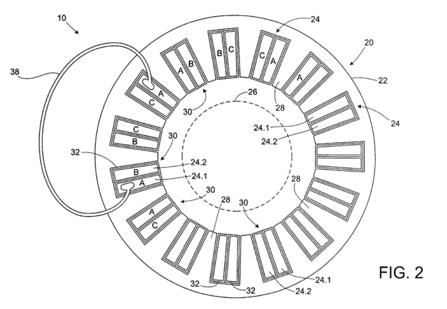
In accordance with the invention, the copper bars 24.1 and 24.2 in each of the slots 30 are interconnected in a predetermined manner at their respective ends. More specifically, the respective ends of the copper bars 24.1 and 24.2 are exposed at the top and bottom of the stator stack 22. The copper bars 24.1 and 24.2 are interconnected with each other such that each copper bar represents a single turn belonging to one of the windings (i.e., the A-phase winding, the B-phase winding or the C-phase winding). The manner in which the windings of the different phases are distributed throughout the slots 30 is conventional in accordance with multi-phase motor winding techniques. The present invention is not intended to be limited(*非限定)to any particular distribution pattern of the different phases as will be appreciated. The present invention is different from conventional winding techniques in the sense that instead of many turns for a given winding being present in a slot, each copper bar within a slot 30 forms only a single turn for a respective winding.
Thus, for example, FIG. 2 illustrates how a given slot 30 includes copper bars 24.1 and 24.2 designated as being a single turn for the A-phase winding and the B-phase winding, respectively. Although shown in FIG. 2 only for two turns each belonging to the A-phase winding, respective turns for the respective windings are electrically connected by an interconnect 38. Each interconnect 38 may be, for example, a wire(*電線、ワイヤ)which is wire bonded to the copper bars 24.1 and 24.2 at respective ends using conventional wire bonding techniques as shown more clearly in FIG. 3. Alternatively, for example, each interconnect 38 may be a conductive bar soldered or welded at respective ends to the copper bars 24.1and 24.2 as shown in FIG. 4.
As will be appreciated by those having ordinary skill in the art, other techniques may be used for forming each interconnect without departing from the intended scope of the invention. For example, the interconnects 38 may be formed using electrodeposition, electrical connectors, soldering, welding, cold forming, stereolithography, etc. The present invention is not necessarily limited to a particular manner for forming the interconnects 38 unless otherwise specified.
Referring to FIG. 5, the interconnects 38 may be used to form the appropriate phase winding interconnections between the copper bar ends on both the top and bottom of the stator assembly 20. In addition, or in the alternative, the copper bars 24.1 and 24.2 may be formed and bent as represented(*示す)in FIG. 6 in order to form a pair of connected turns. For example, the copper bar 24.2 in FIG. 6 is shaped in somewhat of a U-shape(*U形). The sides of the U are inserted into corresponding slots 30 to represent a single turn of a given winding within the slots. The base of the U forms an electrical interconnect between the turns.
FIG. 6A shows another embodiment analogous to the embodiment of FIG. 5, with the exception that(*例外、以外、除いて)the interconnects 38 are formed by particular wiring patterns included in/on a printed wiring board (PWB). The ends of the copper bars 24.1 and 24.2 can be mounted to the respective wiring pattern in/on the PWB(s) using conventional surface mounting techniques, as will be appreciated.
For ease of illustration, it will be appreciated that the drawings herein show only but a few of the interconnections between the turns. However, even with all of the appropriate connections between the copper bars 24.1 and 24.2 for the respective phases, it will be appreciated that the labor associated with making such connections is much less than that required for forming conventional multi-turn windings, particularly with smaller sized motors.
Although the above embodiments have been described primarily in the context of there being only a single turn of a winding in a given slot, it will be appreciated that a larger number of windings could be utilized in a given slot. However, it will be necessary to then provide additional interconnects 38 to interconnect the multiple windings as will be appreciated. Thus, the present invention is preferably limited to a smaller number of turns (i.e., ten or less), within a given slot.
FIG. 7 is a flowchart representing a method for making the stator assembly 20according to an embodiment of FIGS. 1 and 2 of the present invention. In step S50, the stator 22 is formed of a lamination stack with teeth 28 and slots 30. The stator 22 may be formed using conventional stator forming techniques, and thus further detail, is omitted.
In step S52, the winding segments (e.g., copper bars 24.1 and 24.2) for the slots 30 are formed. In one embodiment, the segments are extruded using an electrically conductive material and cut to length. The insulating sheath 32 can be formed separately or as part of the extrusion process. In another embodiment, the segments may be cast in the appropriate shape and length. Although extrusion or casting represent preferred manners for forming the segments, any method may be used without departing from the scope of the invention."
US7737598
"DETAILED DESCRIPTION
Before any embodiments of the invention are explained in detail, it is to be understood that the invention is not limited in its application to the details of construction and the arrangement of components set forth in the following description or illustrated in the following figures. The invention is capable of other embodiments and of being practiced or of being carried out in various ways. Also, it is to be understood that the phraseology and terminology used herein is for the purpose of description and should not be regarded as limiting(*非限定). The use of “including,” “comprising,” or “having” and variations thereof herein is meant to encompass the items listed thereafter and equivalents thereof as well as additional items. Unless specified or limited otherwise, the terms “mounted,” “connected,” “supported,” and “coupled” and variations thereof are used broadly and encompass both direct and indirect mountings, connections, supports, and couplings. Further, “connected” and “coupled” are not restricted to physical or mechanical connections or couplings.
As shown in the FIG. 1 a motor 10 generally includes a rotor 15 disposed within a stator 20. The rotor 15 is mounted on(*取付、取り付け)a shaft 30 that extends axially to provide support points and to provide a convenient shaft power take off(*取出し)point. Generally, two or more bearings 35 engage(*係合)the rotor shaft 30 and support the rotor 15 such that it rotates about a rotational axis 40. The stator 20 is generally fitted into(*嵌入、内に配設)a housing 45. The stator 20 defines a substantially cylindrical aperture, or bore 55 as it is commonly referred to in the motor art, that is centered on(*心合わせ、心出し)the rotational axis 40. When the rotor 15 is in its operating position relative to the stator 20 a small air gap is established(*形成)between the rotor and the stator. The air gap allows for relatively free rotation of the rotor 15 within the stator 20.
The frame 45, if employed, supports the stator 20. One frame 45, better illustrated in FIG. 11, includes a plurality of empty spaces 46 near the corners. The empty spaces 46 provide cooling passages for cooling air or another cooling fluid. In preferred constructions, the frame 45 includes a plastic material that is injection molded or otherwise formed. In other constructions, an extruded aluminum frame is employed. In still other constructions, other materials and other manufacturing methods may be employed to manufacture the frame 45.
The motor 10 illustrated in FIG. 1 is a brushless permanent magnet (PM) motor. As such, the rotor 15 includes a ferromagnetic core and permanent magnets that define two or more magnetic poles. The stator 20 includes one or more phase windings (shown in FIGS. 2-3) that can be selectively energized(*通電)to produce a magnetic field. The permanent magnets of the rotor 15 interact with the magnetic field of the stator 20 to produce electromagnetic torque and rotor rotation. As one of ordinary skill will realize, the invention is also suited for other types of motors, in addition to the brushless permanent magnet motors illustrated herein. As such, the invention should not be limited to only these types of motors. Furthermore, one of ordinary skill in the art will realize that the invention can also be applied to many types of generators. The figures depict a motor 10 configuration having the rotor 15 placed interior to(*内側、内部)the stator 20. However, the invention is also applicable to motor configurations, typically referred to as “inside-out motors,” where the rotor is exterior to(*外側、外部)the stator. In addition, the figures and description presented herein are directed to a stator 20and/or a motor 10. However, many of the features described and illustrated could be applied to wound rotors. Thus, while the figures and description refer to a brushless motor 10 and/or a stator 20, other applications are possible."
当ブログの例文について
本ブログの「特許英語散策」等題した部分では、英語の例文を管理人の独断と偏見で収集し、適宜訳文・訳語を記載しています。
訳文等は原則として対応日本語公報をそのまま写したものです。私個人のコメント部分は(大抵)”*”を付しています。
訳語は多数の翻訳者の長年の努力の結晶ですが、誤訳、転記ミスもあると思いますのでご注意ください。


