GB2353297(DE)
"DE-PS 171185 (corresponding to US-PS 798 130) discloses a said double lockstitch machine, wherein a thread gripper is proposed for holding the looper thread during the formation of the first of a group of stitchesThe thread gripper is controlled by a component formed with a curved groove, that is in a fixed sequence at the beginning of production of a new group of stitches."
【従来の技術】ドイツ国特許第171185号明細書(対応米国特許第798130号明細書)からそのような本縫ミシンが公知であり、その際製造されるべきステッチ群の第1ステッチの形成中に下糸を固定するための糸ばさみ、が提案されている。その際糸ばさみの制御は、カム溝を備えた構成部分によって新たに形成されるべきステッチ群の開始までに確定した予め付与されるプロセスに従って行われる。
US6182589(DE)
"The driving devices of the types specified in the foregoing prior art have the distinct drawback that an attainable rotational speed for the catcher is relatively low at the moment that the loop is picked up by the point of the catcher. However, the rotational speed of the catcher cannot be varied at will with conventional devices known to the prior art, because the driving movements of the needle bar and of the catcher of a double-stitch sewing machine have to be synchronized. As long as the needle moves in a central position, i.e., in the zero position, and is therefore not deflected sideways for zig-zag sewing, the movements of the catcher exactly match the position of the needle."
【0004】冒頭に記載された種類の駆動装置は、釜剣先による糸ループ受渡しの瞬間における釜の到達可能な回転速度が比較的小さいという欠点を有する。しかし釜の回転速度は、公知の駆動装置によっては任意に変えられない、そのわけは本縫ミシンの針棒及び釜の駆動運動は、同期して行われなければならないからである。針が中央の、即ちゼロ位置に移動され即ちジグザグ縫いに設定されてない場合、釜の運動は正確に針位置と一致する。
EP3006616(JP)
"[0028] A lockstitch sewing machine is provided with a needle bar 13 on which a sewing needle 12 is detachably mounted, and a lower shaft 14 which is rotated in a rotation direction A around a rotation axis L2 parallel to an axis L1 of the needle bar 13. At the lower shaft 14 is provided the horizontal full rotating hook 11 comprising an outer shuttle 17 which has a blade point portion 15 which is tapered so that a tip portion thereof is directed toward the downstream side in the rotation direction A, and a needle guard 16 which is tapered so that a tip portion thereof is directed toward the upstream side in the rotation direction A and is disposed further toward the downstream side in the rotation direction A than the blade point portion 15, and the inner shuttle 18 which is accommodated in the outer shuttle 17, and the needle-handler position adjusting device 10 of this embodiment is provided in the horizontal full rotating hook 11."
本縫ミシンには、縫い針12が着脱可能に取付けられる針棒13と、針棒13の軸線L1に平行な回転軸線L2まわりに回転方向Aに回転駆動される下軸14とが設けられる。下軸14には、回転方向A下流側に先端部を向けて先細状となる剣先部15を有し、剣先部15よりも回転方向A下流側に、該回転方向A上流側に先端部を向けて先細状となる針寄せ板16が配設される外かま17と、外かま17に収容される内かま18とを備える水平全回転かま11が設けられ、この水平全回転かま11に本実施形態の針寄せ位置調整装置10が設けられる。
最新の画像[もっと見る]
-
 凡例
5日前
-
 バズリクソンズA2:第18週
1週間前
-
 バズリクソンズA2:第17週
2週間前
-
 バズリクソンズA2:第16週
4週間前
-
 DAZN(ダゾーン):メール配信停止ボタンくらい付けとけ
1ヶ月前
-
 DAZN(ダゾーン):メール配信停止ボタンくらい付けとけ
1ヶ月前
-
 バズリクソンズA2:第15週
1ヶ月前
-
 バズリクソンズA2:第14週
1ヶ月前
-
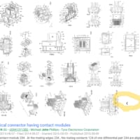
 Google Patents Advanced Searchで全部表示される図面の表示を隠す
1ヶ月前
-
 召合せ框(めしあわせかまち)
2ヶ月前


※コメント投稿者のブログIDはブログ作成者のみに通知されます