


US2019382161
[0039] FIG. 4 illustrates an exemplary container 1 that includes an activated polymeric closed-bottom cylindrical insert 10 disposed within the enclosure member 2. Activation of the polymeric insert is conducted through methods as described herein.
図4は、囲い部材2内に配置される活性ポリマー有底の円柱状インサート10を含む例示的容器1を示す。ポリマーインサートの活性化は、本明細書に記載される方法によって行われる。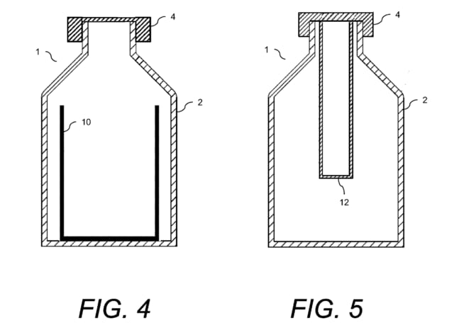
For purposes of maximizing surface area of the active polymeric surface, it is preferred that each of the exposed surfaces of the cylindrical assembly are activated. The cylindrical assembly can be manufactured by methods known in the art, for example, extrusion blow molding.
活性ポリマー表面の表面積を最大にする目的上、円柱状の組立体の露出した表面のそれぞれが活性化されることが好ましい。円柱状組立体は、当技術分野で既知の方法、例えば押出ブロー成形によって製造できる。
US10610235
Additionally, even when the end 15A is provided with a through hole, like the modification shown in FIG. 30A, the through hole 22 may be formed by extending the end 15A, and like the modification shown in FIG. 30B, a stepped portion 23 may be provided by cutting or the like and the stepped portion 23 may be formed with a through hole 23A.
【0099】
更に、図30Aに示す変形のように、端部15Aに、貫通穴が備えられる場合でさえ、貫通穴22が、端部15Aを延在することによって形成されてもよく、図30Bに示す変形のように、段差部分23は、切断などによって設けられてもよく、段差部分23は、貫通穴23Aを有して形成することができる。
Moreover, like the modification shown in FIG. 31, a bottomed recess 24 may be provided instead of a through hole.
その上、図31に示す変形のように、貫通穴の代わりに有底の陥凹24を設けてもよい。


※コメント投稿者のブログIDはブログ作成者のみに通知されます