


WO2017142817
The microdriver chip devices (e.g. driver transistors, emission control transistors, switching transistors, etc.) may be formed in the device layer and interconnected in the build-up layer 106,
マイクロドライバチップデバイス(例えば、ドライバトランジスタ、発光制御トランジスタ、スイッチングトランジスタなど)はデバイス層に形成かつビルドアップ層106にて相互配線することができ、
which may include one or more interconnect layers (e.g. copper interconnects) and insulating layers (e.g. interlayer dielectrics, ILDs),
ビルドアップ層は、1つ以上の相互配線層(例えば、銅相互配線)及び絶縁層(例えば、層間絶縁膜、ILD;interlayer dielectric)を含むことができ、
culminating in a plurality of landing pads 110 at the top of the build-up layer 106. For example, the landing pads 110 may be formed of copper.
複数のランディングパッド110としてビルドアップ層106の上部で頂点に達する。例えば、ランディングパッド110を銅で形成することができる。
US2020017972
In one embodiment, substrate 901 includes metallization interconnect layers for integrated circuits.
一実施形態では、基板901は、集積回路用の金属被覆配線層を含む。
In one embodiment, substrate 901 includes electronic devices, e.g., transistors, memories, capacitors, resistors, optoelectronic devices, switches, and any other active and passive electronic devices that are separated by an electrically insulating layer, for example, an interlayer dielectric, a trench insulation layer, or any other insulating layer known to one of ordinary skill in the art of the electronic device manufacturing.
一実施形態では、基板901は、例えばトランジスタ、メモリ、コンデンサ、レジスタ、光電子デバイス、スイッチ、及び例えば層間絶縁膜、トレンチ絶縁層、又は電子デバイス製造業者に周知の他の何らかの絶縁層等の電気絶縁層によって分離された他の任意の能動及び受動電子デバイス等の電子デバイスを含む。
In at least some embodiments, substrate 901 includes interconnects, for example, vias, configured to connect the metallization layers.
少なくとも幾つかの実施形態では、基板901は、金属層を接続するように構成された例えばビア等の配線を含む。
In one embodiment, substrate 901 is a semiconductor-on-isolator (SOI) substrate including a bulk lower substrate, a middle insulation layer, and a top monocrystalline layer.
一実施形態では、基板901は、バルク下部基板、中間絶縁層、及び上部単結晶層を含む絶縁膜上に半導体が形成された(SOI)基板である。
The top monocrystalline layer may comprise any material listed above, e.g., silicon.
上部単結晶層は、例えばシリコン等の上述したいずれかの材料を含みうる。
WO2012173770
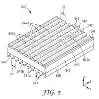
In alternate embodiments, the threshold between Ii and I2 is
代替の実施形態では、I1とI2の間の閾値は、
demarked by a threshold associated for any of the mask material (generally in the range of 0.0001 GW/cm and 0.001 GW/cm ), dielectric layer of the thin film device layer stack 401 (generally in the range of O.lGW/cm and lOGW/cm ), or an interconnect layer of the thin film device layer stack 401 (generally be in the range of 0.01G W/cm and 0. lGW/cm ).
マスク材料(概して、0.0001GW/cm2~0.001GW/cm2の範囲内)、薄膜デバイス層スタック401の誘電体層(概して、0.1GW/cm2~10GW/cm2の範囲内)、又は薄膜デバイス層スタック401の配線層(概して、0.01GW/cm2~0.1GW/cm2の範囲内である)のうちの何れかに関連する閾値によって画定される。
WO2018236682
[0004] In particular, FIG. 1 illustrates a metal layout of a conventional semiconductor device 10 that includes a gate pad 12, a source pad 22 and a drain pad 32 on a semiconductor structure 20.
【0004】
特に図1は、半導体構造20上の、ゲート・パッド12、ソース・パッド22、及びドレイン・パッド32を含む、従来の半導体デバイス10のメタル層レイアウトを示す。
FIG. 1 is a plan view of the semiconductor device (i.e., looking down at the device from above) that illustrates various metal contact structures of the semiconductor device 10 that are formed on the underlying semiconductor structure 20.
図1は、基礎となる半導体構造20の上に形成された半導体デバイス10の様々なメタル層コンタクト構造を示す、半導体デバイスの平面図(すなわち、デバイスを上方から見下ろす図)である。
As shown in FIG. 1, in the conventional semiconductor device 10, the gate pad 12 is connected by a gate bus 14 to a plurality of gate fingers 16 that extend in parallel in a first direction (e.g., the y-direction indicated in FIG. 1).
図1に示すように、従来の半導体デバイス10では、ゲート・パッド12がゲート・バス14により、第1の方向(たとえば、図1に示すy方向)に並行して伸びる複数のゲート・フィンガー16に接続する。
The drain pad 32 is connected to a plurality of drain contacts 36 via a drain bus 34.
ドレイン・パッド32は、ドレイン・バス34を介して複数のドレイン・コンタクト36に接続する。
The source pad 22 is connected to a plurality of parallel source contacts 26 via a source bus 24 that is disposed at(*onも可?)a different metallization layer (here a higher metallization layer that runs above the gate fingers 16 and the drain contacts 36).
ソース・パッド22は、異なる配線層(ここではゲート・フィンガー16及びドレイン・コンタクト36の上方を走る(*延在)、より上層の配線層)に配置するソース・バス24を介して、複数の並列ソース・コンタクト26に接続する。

Vertically-extending (i.e., extending in a z-direction that is perpendicular to the x-direction and the y-direction) source contact plugs 28 electrically connect each source contact 26 to the source bus 24.
縦方向に伸びる(すなわち、x方向とy方向とに垂直なz方向に伸びる)ソース・コンタクト・プラグ28は、電気的に各ソース・コンタクト26をソース・バス24に接続する。
EP3396742
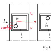
[0029] With respect to the IC process, nodes may typically be differentiated by the minimum feature size of a transistor, such as its "so-called" transistor channel.
【0048】
ICプロセスに関して、ノードは、トランジスタにおける「いわゆる」チャネルなどの、トランジスタの最小機能部寸法によって差別化され得る。
This physical feature, along with other parameters of the IC fabrication, such as gate oxide thickness, may be associated with a resulting rating standard for "turn-on" or "threshold" voltages of field-effect transistors (FET's) fabricated in the given process node.
この物理的特徴部は、他のIC製造パラメータ(ゲート酸化膜厚など)と共に、所与のプロセスノードに製造された電界効果トランジスタ(FET)の、得られる「ターンオン」時定格標準、又は「閾値」電圧と関連付けることができる。
For example, in a node with a minimum feature size of 0.5 microns, it may be common to find FET's with turn-on voltages of 5.0V. However, at a minimum feature size of 90 nm, the FET's may turn-on at 1.2, 1.8, and 2.5V.
例えば、最小特徴寸法が0.5マイクロメートルのノードでは、FETのターンオン電圧は5.0Vであることが通常であり得る。しかしながら、90nmの最小特徴寸法では、FETは、1.2、1.8、及び2.5Vでターンオンし得る。
The IC foundry may supply standard cells of digital blocks, for example, inverters and flip-flops that have been characterized and are rated for use over certain voltage ranges.
IC製造工場は、ある特定の電圧範囲での使用に特徴付けられ、定格を定められた、例えばインバーターやフリップフロップのようなデジタルブロックの標準的なセルを供給し得る。
Designers chose an IC process node based on several factors including density of digital devices, analog/digital mixed signal devices, leakage current, wiring layers, and availability of specialty devices such as high-voltage FET's.
設計者は、デジタル素子の密度、アナログ/デジタル混合信号素子、リーク電流、配線層、及び高圧FETのような特殊素子のアベイラビリティといったいくつかの要因に基づいて、ICプロセスノードを選択する。
Given these parametric aspects of the electrical components, which may draw power from a microbattery,
超小型電池から電力を引き出すことができる電気部品のこうしたパラメータに関する側面を前提として、
it may be important for the microbattery power source to be matched to the requirements of the chosen process node and IC design, especially in terms of available voltage and current.
超小型電池の電源を、特に利用可能な電圧及び電流の点で、選択したプロセスノード及びIC設計の要件に一致させることが重要となり得る。


※コメント投稿者のブログIDはブログ作成者のみに通知されます