


2022-05-16
またまた寄り道です。
▼下記ブログでで書いた様にRC化の新しいツールを勉強中です。
いろいろ試している中で、何とかRCカーに利用できるところまでできました。
▼という事で、2年前にArduino pro miniで完成しているミニ四駆ランクルに換装しました。
▼画像の上がArduino pro mini+ミニUSBホストシールド(Bluetooth USBアダプタ装着)、
下がM5Stamp PICOです。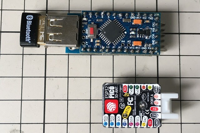
▼M5Stamp PICOをセット。

換装して動作確認すると動かない。
プログラムや接続などチェックすると、リード線がはんだ付け部であちこち切れていました。
こんな事を繰り返して、やっと完成。
以下に、備忘録としてプログラムと回路を残します。
【スケッチを書き込む準備】
(注1)サーボを制御するために「ESP32Servo.h」をインストール。
(注2)ESP32ライブラリV1.0.4をインストール。
(注3)下記スケッチをM5Stamp PICOに書き込み実行。
void setup(void) {
Serial.begin(115200);
uint8_t btmac[6];
delay(500);
esp_read_mac(btmac, ESP_MAC_BT);
Serial.printf("[Bluetooth] Mac Address = %02X:%02X:%02X:%02X:%02X:%02X\r\n", btmac[0], btmac[1], btmac[2], btmac[3], btmac[4], btmac[5]);
}
void loop() {
}
シリアルモニタにアドレスが表示されるのでメモしておく。
次に、SixaxisPairTool でPS3のコントローラにMac Addressを書き込む。
1. PS3コントローラをMiniUSBケーブルでPCに繋ぐ。
2. SixaxisPairToolを実行し、メモしたアドレスを入力してUpdateボタンを押すと書き込みが完了。
(参考)「ESP32でPS3コントローラを使う」をキーにネット検索すると参考になる記述が見つかります。
▼スケッチ(プログラム)/Arduino IDE用
- /*PS4BT_Arduino_DRV8835_RCCAR_04a
- 2020/05/14
- PS4BT_Arduino_DRV8835_RCCAR_02a
- 左十字キーTRIANGLEで高速モード、CROSSで低速(70%)モード
- ステアリング角度をスティック角比例にする
- モータドライバはDRV8835
- 3ピンでステアリングサーボを動かす
- */
- #include <Arduino.h> // Arduino ヘッダインクルード
- #include "M5Atom.h"
- #include <FastLED.h> // LED操作用ライブラリインクルード(3.5.0を使用)
- #define NUM_LEDS 1
- #define DATA_PIN 27
- CRGB leds[NUM_LEDS];
- #include <Ps3Controller.h>
- #include <ESP32Servo.h>
- Servo servo1; // create four servo objects
- int servo1Pin = 26;
- int servo_pos = 90;
- int ang = 40;
- int d_time = 10;
- float ratio = 0.6;
- int pos_y;
- int pos_x;
- float motor_speed;
- float steering;
- int PWMApin = 25; // A入力2/AENABLE 左モータ AIN2
- int PWMA = 11; //PWMAチャンネル 11
- int AIN1 = 22; // A入力1/APHASE 左モータ AIN1
- int LED_3 = 19 ; // ブレーキランプ
- int LED_2 = 18 ; // フォグランプ
- int LED_8 = 21 ; // ヘッドランプ
- void onConnect() {
- Serial.println("Connected.");
- for (int cnt = 0; cnt
- digitalWrite(LED_8, HIGH);
- delay(500);
- digitalWrite(LED_8, LOW);
- delay(500);
- }
- }
- void setup() {
- Serial.begin(115200);
- M5.begin(false, false , true); //SerialEnable, I2CEnable ,DisplayEnable
- FastLED.addLeds<SK6812, DATA_PIN, RGB>(leds, NUM_LEDS); // GRB ordering is typical
- leds[0] = 0xf00000; //green
- ledcSetup(PWMA, 5000, 8); //チャンネル,周波数,解像度(8bit=256段階)
- ledcAttachPin(PWMApin, PWMA); //ledPinをPWMCHチャンネルに接続
- pinMode(AIN1, OUTPUT);
- pinMode(LED_2, OUTPUT);
- pinMode(LED_3, OUTPUT);
- pinMode(LED_8, OUTPUT);
- servo1.setPeriodHertz(50); // Standard 50hz servo PWMサイクル:20mS
- servo1.attach(servo1Pin, 500, 2400); // (servo1Pin, minUs, maxUs)
- servo1.write(servo_pos);
- Ps3.attachOnConnect(onConnect);
- Ps3.begin("00:11:22:33:44:55"); //SixaxisPairToolで調べたmac adresに修正
- Serial.println("Ready");
- }
- void loop() {
- if (Ps3.isConnected()) {
- pos_y = Ps3.data.analog.stick.ly;
- pos_x = Ps3.data.analog.stick.rx;
- pos_y = pos_y + 128;
- pos_x = pos_x + 128;
- if (Ps3.event.button_down.triangle) {
- ratio = 1; //高速モード
- }
- if (Ps3.event.button_down.cross) {
- ratio = 0.7; //低速モード
- }
- if (pos_x >= 152 ) { // R
- //steering = map(pos_x, 152, 255, 0, 45);
- steering = map(pow(pos_x, 2), 23104, 65025, 0, 55 );
- servo1.write(servo_pos - steering);
- //delay(d_time);
- } else {
- if (pos_x <= 103 ) { //L
- //steering = map(pos_x, 103, 0, 0, 35);
- steering = map(pow(pos_x, 2), 10609, 0, 0, 55 );
- servo1.write(servo_pos + steering);
- //delay(d_time);
- }
- else {
- servo1.write(servo_pos);
- }
- }
- //左スティックがセンター付近は停止(ブレーキ)
- if ( pos_y > 117 && pos_y
- motor_run(0, 0, 1);
- }
- //前進
- else if (pos_y
- //左スティック中央(117)から最上部(0)の値をモーターのスピード0から255に変換
- // motor_speed = ratio * map(pos_y, 117, 0, 0, 255);
- motor_speed = ratio * map(pow(pos_y, 2), 13689, 0, 0, 255 );
- motor_run(motor_speed, 1, 0);
- }
- //後進
- else if ( pos_y > 137) {
- //motor_speed = ratio * map(pos_y, 137, 255, 0, 255);
- motor_speed = ratio * map(pow(pos_y, 2), 18769, 65025, 0, 255 );
- motor_run(motor_speed, 0, 0);
- }
- //ヘッドライト
- if (Ps3.event.button_down.right) { //点灯
- digitalWrite(LED_8, HIGH);
- }
- if (Ps3.event.button_down.left) { //消灯
- digitalWrite(LED_8, LOW);
- }
- //フォグランプ
- if (Ps3.event.button_down.up) { //点灯
- digitalWrite(LED_2, HIGH);
- }
- if (Ps3.event.button_down.down) { //消灯
- digitalWrite(LED_2, LOW);
- }
- }
- }
- void motor_run(float D0, int D1, int D4) {
- //SPrint();
- /* D0 : モータスピード(左)
- D1 : モータA(左)1 = HIGH / 0 = LOW
- D4 : LED_3 ON/OFF 1 = HIGH / 0 = LOW
- */
- //analogWrite(PWMA, D0);
- ledcWrite(PWMA, D0); //(チャンネル,解像度)
- digitalWrite(AIN1, D1);
- digitalWrite(LED_3, D4);
- }
▼回路図
画像をクリックすると拡大します
▼Arduino IDE ボードの設定