これからの転載は、GhostRiponさん(HN)の力作、傑作、
それではまだ言い足りない........。
勝れた業績である!!
詳しく読めば、誰でも水で走る車、水で起こす電気、水を利用して、
エネルギー革命が出来る!!
今回は、電気回路についての解説であるから、門外漢には少々、読むのに難解な部分が多い。読み飛ばしていただだいても結構。
本転載は、実地に製作可能な情報を細大漏らさず提供することを目的としている。それが、元記事作者の意図でもある。そうでない方は、概念を諒解するに留めて置く場合、さらっと読んで頂いても結構という意味である。
又、拡散の意図もあるから、細大漏らさず転載する訳をご了承頂きたい。。
要約すると、特定の電磁パルスを発生させる回路のようである。詳しい方は、再現可能と考えるが、投稿者は残念ながらエンジニアではない。製作実施は無理である。只、要領は理解できる。要するに水分子を効果的に酸素分子、水素分子に分離することが出来る電気力学が存在すると言うことだ。それは特定電磁パルスを発生する必要がある。その発生回路と言うことだ。
そのパルス波形も次第に明らかとなる。この記事は特許に基づいて書かれてある。巻末にはその特許公報もPDFファイルでダウンロードできるのでご覧なられると良い。既に特許期限は消滅していると言うことである。
【転載開始】2009年09月05日(土)
Pulsed Water-splitters No.3(パルスを用いた水の分解)
テーマ:エコ&エネルギー
A Practical Guide to Free-Energy Devices
Author: Patrick J. Kelly
Chapter 10: Automotive Systems No.3
http://www.free-energy-info.co.uk/Chapt10.html
This is the section of the circuit which does this:
回路の役割については、セクションごとにわかれてます:
The
100 ohm resistor and the 100 microfarad capacitor are there to iron out
any ripples in the voltage supply to the circuit, caused by fierce
pulses in the power drive to the electrolysis cell. The capacitor acts
as a reservoir of electricity and the resistor prevents that reservoir
being suddenly drained if the power supply line is suddenly, and very
briefly, pulled down to a low voltage. Between them, they keep the
voltage at point “A” at a steady level, allowing the 555 chip to operate smoothly.
100Ω
抵抗と100μFコンデンサーは、電気分解セルを強烈なパルスでパワードライブさせる回路への電圧供給において機能します。
コンデンサと抵抗器は、電力を貯める機能をし、突然の電圧降下を防ぐために機能します。それらの間では、555チップがスムーズに作動し、ポイント「A」
で安定した電圧を保ちます。
The very small capacitor “B”
is wired up physically very close to the chip. It is there to
short-circuit any stray, very short, very sharp voltage pulses picked
up by the wiring to the chip. It is there to help the chip to operate
exactly as it is designed to do, and is not really a functional part of
the circuit. So, for understanding how the circuit works, we can ignore
them and see the circuit like this:
非常に小さな容量の
10nFコンデンサー「B」は、物理的にチップの近くに配線されます。非常に短く、非常に鋭い電圧パルスは、チップへの配線によってピックアップされま
す。小さいコンデンサーの目的は、回路の機能的な部品ではく、チップが正確に動作することを手助けするために、そこに配置されてます。従って、どのように
回路が作動するかを理解するためには、それを無視して構いません:
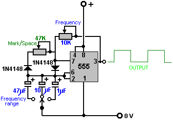
This
circuit generates output pulses of the type shown in green with the
voltage going high, (the “Mark”) and low (the “Space”). The 47K
variable resistor (which some people insist on calling a “pot”) allows
the length of the Mark and the Space to be adjusted from the 50 - 50
shown, to say, 90 - 10 or any ratio through to 10 - 90. It should be
mentioned that the “47K” is not at all critical and these are quite
likely to be sold as “50K” devices. Most low cost components have a
plus or minus 10% rating which means that a 50K resistor will be
anything from 45K to 55K in actual value.
この回路は
電圧が高く(“Mark”)、低く(“Space”)出力し、緑色のラインで描かれている形状の出力パルスを発生させます。47Kの可変抵抗器(人々が
“pot”と呼ぶ)による出力パルスの長さ調整は、50-50を中心として、比率90-10~10-90の範囲で変更可能にします。「47K」が決定的な
選択ではなく、似たような可変抵抗器で「50K」もあり、販売されています。最も低コストのコンポーネントは、「50K」の抵抗でプラスマイナス10%の
調整範囲のもので、抵抗値は45K~55K相当になります。
The two “1N4148” diodes are
there to make sure that when the Mark/Space 47K variable resistor is
adjusted, that it does not alter the frequency of the output waveform
in any way. The remaining two components: the 10K variable resistor and
the 47 microfarad capacitor, both marked in blue, control the number of
pulses produced per second. The larger the capacitor, the fewer the
pulses per second. The lower the value of the variable resistor, the
larger the number of pulses per second.
2つ
の"1N4148"ダイオードを装着して、47Kの可変抵抗器で調整された時、出力波形の周波数が変更されないようにします。残りの2つのコンポーネン
ト:10Kの可変抵抗器と47μFコンデンサの両方(青色でマーク)は、1秒あたりのパルス生産数を制御します。コンデンサの容量が大きいほど、1秒あた
りのパルス数が少なくなります。可変抵抗器の値が低いほど、1秒あたりのパルス数が大きい。
The circuit
can have additional frequency tuning ranges, if the capacitor value is
altered by switching in a different capacitor. So the circuit can be
made more versatile by the addition of one switch and, say, two
alternative capacitors, as shown here:
もしも、コンデンサの値を別のコンデンサに切り替えるならば、この回路は、追加の周波数範囲を変更、調整することができます。そのため、回路に切替スイッチを加えることによって多目的な、たとえば、2つの代替コンデンサを追加して、以下に示すように行うことができます:
The
capacitors shown here are unusually large because this particular
circuit is intended to run relatively slowly. In the almost identical
section of the circuit which follows this one, the capacitors are very
much smaller which causes the switching rate to be very much higher.
Experience has shown that a few people have had overheating in this
circuit when it is switched out of action, so the On/Off switch has
been expanded to be a two-pole changeover switch and the second pole
used to switch out the timing elements of the 555 chip. The complete
version of this section of the circuit is then:
こ
こに示されたコンデンサー容量は異常に大きい。なぜなら、この特定の回路は、ゆっくり相対的に動くことを意図しているからです。一方、同一回路の別セク
ションでは、非常に小さい容量のコンデンサーを使い、切り換えレートを非常に高く行っている。少数の人々の報告によれば、この回路の切り替え時に、過熱し
たようなので、オン/オフの2極切換スイッチを追加して、555チップのタイミング信号を使って切り替えるようにうに拡張されている。回路のこのセクショ
ンの完全なバージョンは以下です:
which
just has one additional switch to allow the output to be stopped and
the 12-volt supply line to be fed instead. The reason for this is that
this part of the circuit is used to switch On and Off an identical
circuit. This is called “gating” and is explained in Chapter 12 which
is an electronics tutorial.
12Vの出力を停止することができる追加
スイッチを設けて、12Vの電源ラインの代わりに供給する。
その理由は、同一の回路を切り替えるために、回路の同じ部分が使用されることです。これは、「ゲート回路」と呼ばれて、電子機器のチュートリアルである第
12章で説明されます。
The second part of the circuit is intended to run at much higher speeds, so it uses much smaller capacitors:
第2回路の部分は、より高い速度で動作するので、はるかに小さい容量のコンデンサを使用します:
So, putting them together, and allowing the first circuit to switch the second one On and Off, we get:
従って、それらをまとめて、最初の回路が第2回路を制御することを可能にしました:
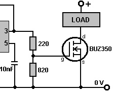
The
final section of the circuit is the power drive for the electrolyser
cell. This is a very simple circuit. Firstly, the output of the second
555 chip is lowered by a basic voltage-divider pair of resistors, and
fed to the Gate of the output transistor:
回路の
最終的なセクションは、電解槽セルのためのパワードライブです。これは非常にシンプルな回路です。まず、2番目の555チップから出力された電圧は、分圧
回路(抵抗分割回路)としての2つの抵抗器により引き下げられ、そして、出力トランジスタのゲートにフィードバックされます:
Here,
the 555 chip output voltage is lowered by 220 / 820 or about 27%. When
the voltage rises, it causes the BUZ350 transistor to switch on,
short-circuiting between its Drain and Source connections and applying
the whole of the 12-volt supply voltage across the load, which in our
application, is the electrolyser cell:
ここでは、555チップの出力電圧は、220Ω÷820Ωまたは約27%下げられます。出力電圧が上がると、BUZ350トランジスタのスイッチが入り、12Vの供給電圧が流れこみ電極チューブをショートさせます。それが電解槽セルのしくみです:
The
transistor drives the electrolysis electrodes as shown above, applying
very sharp, very short pulses to them. What is very important are the
wire coils which are placed on each side of the electrode set. These
coils are linked magnetically because they are wound together on a
high-frequency ferrite rod core and although a coil is such a simple
thing, these coils have a profound effect on how the circuit operates.
Firstly, they convert the 555 chip pulse into a very sharp, very short,
high-voltage pulse which can be as high as 1,200 volts. This pulse
affects the local environment, causing extra energy to flow into the
circuit. The coils now perform a second role by blocking that
additional energy from short-circuiting through the battery, and
causing it to flow through the electrolysis cell, splitting the water
into a mix of hydrogen and oxygen, both gases being high-energy, highly
charged atomic versions of those gases. This gives the mix some 400%
the power of hydrogen being burned in air.
トランジ
スタは、非常に鋭くて、非常に短いパルスを電気分解電極に適用して、上に示されているように動作させます。非常に重要なものは、セル(電極チューブ)の側
に置かれているバイファイラーコイルです。コイルは高周波フェライト棒コア上に一緒に巻き上げられてます。そして、このコイルの構造は非常に単純なもので
あるが、回路がどう作動するかの甚大な効果があります。これらのコイルは磁力によってリンクされます。バイファイラーコイルは、555チップが作り出した
パルスを、非常に鋭く、非常に短く、高電圧(約1200V)に変換します。このパルスはローカルな環境に影響し、追加エネルギーを回路に流入させます。コ
イルの2つめの役割は、バッテリーを高電圧によるショートから守ります、そして、高電圧が電解セルを通して流れることで水を、水素と酸素の混合ガスに分解
します、両者共に原子ガス(HHO)バージョンで、高エネルギーである。水素原子混合ガスは、空気中で水素分子が燃焼する熱エネルギーの約400%
(3.8倍)の熱エネルギーを放出します。(この特徴は、ブラウン・ガスと同じ)
When
the transistor switches off, the coils try to pull the transistor Drain
connection down to a voltage well below the 0-volt battery line. To
prevent this, a 1N4007 diode is connected across the cell and its
coils. The diode is connected so that no current flows through it until
the transistor Drain gets dragged down below the 0-volt line, but then
that happens, the diode effectively gets turned over and as soon as 0.7
volts is placed across it, it starts to conduct heavily and collapses
the negative voltage swing, protecting the transistor, and importantly,
keeping the pulsed waveform restricted to positive DC pulses, which is
essential for tapping this extra environmental energy which is what
actually performs the electrolysis. You can easily tell that it is the
environmental “cold” electricity which is doing the electrolysis as the
cell stays cold even though it is putting out large volumes of gas. If
the electrolysis were being done by conventional electricity, the cell
temperature would rise during the electrolysis. A John Bedini pulser
circuit can be used very effectively with a cell of this type and it
adjusts automatically to the resonant frequency as the cell is part of
the frequency-determining circuit.
トランジスタのスイッチが
OFFのとき、コイルは、トランジスタのドレン(d)接続を抜き取り、バッテリー線の電圧を0Vまで下げようとします。これを防止するために、セルおよび
そのコイルを横切って1N4007ダイオードが接続されます。ダイオードが接続されて
0ボルトラインに引きずられるので、電流はトランジスタのドレン(d)まで全く流れません、しかし、ダイオードは順方向電圧が0.7Vに達しないと電流が
ながれません。スタート時の動作は重く、負の電圧振幅を潰しトランジスタを保護します。そして重要なのは、直流パルス化された波形を(+)に限定されるよ
うにしておくこと、それらは、電解を実行するのに追加されるであろう周囲のエネルギーを利用するのに不可欠なものです。電解セルが電気分解をして大量の水
素混合ガスを放出しても、冷たいまま(発熱しない)なので、あなたは、環境に配慮した「冷たい」電気であると簡単に言うことができます。もしも、従来通り
の電気分解が行われるなら、セル温度は電気分解の間、上昇することでしょう。ジョンBedini氏のパルス回路は、このタイプのセルを使用することで非常
に効果的に使用されます、そして、セルが周波数決定する回路の一部であるので、それは自動的に共振周波数に調整されます。
The
BUZ350 MOSFET has a current rating of 22 amps so it will run cool in
this application. However, it is worth mounting it on an aluminium
plate which will act as both the mounting and a heat sink but it should
be realised that this circuit is a bench-testing circuit with a maximum
current output of about 2 amps and it is not a Pulse-Width Modulation
circuit for a high-current DC electrolyser. The current draw in this
arrangement is particularly interesting. With just one tube in place,
the current draw is about one amp. When a second tube is added, the
current increases by less than half an amp. When the third is added,
the total current is under two amps. The fourth and fifth tubes add
about 100 milliamps each and the sixth tube causes almost no increase
in current at all. This suggests that the efficiency could be raised
further by adding a large number of additional tubes, but this is
actually not the case as the cell arrangement is important. Stan Meyer
ran his VolksWagen car for four years on the output from four of these
cells with 16-inch (400 mm) electrodes, and Stan would have made a
single larger cell had that been feasible.
BUZ350
MOSFET [電界効果トランジスタ(FET)の一種、パワーMOSFET(英:Power
MOSFET)、大電力を取り扱うように設計されたMOSFETのこと。
他のパワーデバイスと比較するとスイッチング速度が速く、低電圧領域での変換効率が高い為、200V以下の領域で、スイッチング電源や、DC-DCコン
バータ等に用いられる。]
は、22Aの定格電流なので、動作中は涼しく動くでしょう。しかし、それを実装するとき、アルミニウムプレート上に設置することや、同様にアルミのヒート
シンクをつけることは価値があります。しかし、この回路が約2Aの最大電流出力ベンチテスト回路であり、大電流(直流)で電気分解をするための、
PWM(パルス幅変調回路)でないことを理解するべきです。そして、次に書く電流の流れ方は、特に興味深いものです。1つのチューブがある時は、電流は約
1Aです。2番目のチューブが追加されると、電流は0.5A以下で増加します。3番目のチューブが追加されると、全体の電流は2A弱になります。4番目と
5番目のチューブが追加されると、それぞれ約100mAで増大します。そして、6番目のチューブは、追加されても電流はほとんど増加しません。これは、
チューブを多数追加することによって、効率がさらに良くなる可能性を示
していますが、事例として、チューブの配置の方が重要(分解効率に影響する)なので、本数はそれほど重要ではありません。スタンマイヤー氏は、4本の電極
チューブ、長さ16インチ(400mm)の(水素混合ガス)アウトプットにおいて、彼のフォルクスワーゲンを4年間走らせました。そして、本数や配置が重
要でなければ、スタン氏は単一のより大きいセルを作ったことでしょう。
Although
the current is not particularly high, a five or six amp
circuit-breaker, or fuse, should be placed between the power supply and
the circuit, to protect against accidental short-circuits. If a unit
like this is to be mounted in a vehicle, then it is essential
that the power supply is arranged so that the electrolyser is
disconnected if the engine is switched off. Passing the electrical
power through a relay which is powered via the ignition switch is a
good solution for this. It is also vital that at
least one bubbler is placed between the electrolyser and the engine, to
give some protection if the gas should get ignited by an engine
malfunction.
電流は特に高くはありませんが、5Aまたは6Aの回路ブレーカーまたは
ヒューズは、偶然のショートに対して保護を目的に、電源と回路の間に配置する必要があります。もしこのような電解槽を乗り物に設置する場合は、エンジンを
停止した時に電解槽の接続も切れるように配線されることが必要です。イグニション・スイッチを通して動かされるリレーに配線を通すのが、良い解決策です。
また、少なくとも1個のbubbler(上の図)が電解槽とエンジンの間に置かれることも、安全上重要であり、エンジンの点火によって起こるガス引火
(バックファイア)から、電解槽を保護するためにも必要です。
感想:
回路の説明は、理解できた範囲でのフィーリング意訳。
解釈が逆になっている場合も考えられますので、怪しい部分は原文で確認してください。
わかったことは、スタンマイヤー氏のセルから発生するガスも、ブラウンガスとおなじ原子水素ガスだったようです。
ブラウンガスは、溶接機ですでに実用化されているので、ここで書かれている内容についても信憑性が相当
高くなったと思います。
そう考えると、スタンマイヤー氏の自動車(エンジン)は、爆縮で動かしていたように思えます。
ブラウンガスが、どのようなセルで分解しているのかわかりませんが、分解装置は実在しているので
このセルも分解できる可能性が、非常に高いと言える。(と言うかできると思います)
国も違い、考え方も違った2人が共に辿り付いた結論が、原子水素ガスとは・・・ 興味深いです。
次回は、回路に使用される構成部品についてです。
Pulsed Water-splitters No.4(パルスを用いた水の分解)
http://ameblo.jp/ghostripon/entry-10333372780.html
■過去の記事
Pulsed Water-splitters No.1(パルスを用いた水の分解)
http://ameblo.jp/ghostripon/entry-10330994478.html
Pulsed Water-splitters No.2(パルスを用いた水の分解)
http://ameblo.jp/ghostripon/entry-10331992718.html
■関連記事
Stanley Meyer Data特許資料(英文) [pdf 221ページ]
http://www.free-energy-info.co.uk/MeyerData.pdf
Stanley Meyer - It Runs On Water(水で走る自動車)
http://ameblo.jp/ghostripon/entry-10328859717.html
【資料】Stanley Meyer - It Runs On Water(水で走る自動車)
http://ameblo.jp/ghostripon/entry-10330431267.html
原子水素ガス - HHO GAS - ブラウン・ガス -
http://ameblo.jp/ghostripon/entry-10323958738.html
【続】原子水素ガス - HHO GAS - ブラウン・ガス -
http://ameblo.jp/ghostripon/entry-10328872198.html
燃える塩水 - Salt Water -
http://ameblo.jp/ghostripon/entry-10323134471.html
Byron New Energy - チャージ水 - charged water -
http://ameblo.jp/ghostripon/entry-10324533613.html
【転載終了】


