


Make中国語版です。
爱上制作 とは「製作を愛する」ということか。
爱上制作 とは「製作を愛する」ということか。

/*
ikkeiplexing ( Charlieplexing by ikkei )
Use dual 8x8 dot matrix LED
Moving Dot advanced
edited by ikkei 2010.08.22
*/
#include <MsTimer2.h>
#define A1 6
#define A2 10
#define A3 17
#define A4 2
#define A5 14
#define A6 3
#define A7 9
#define A8 5
#define K1 1
#define K2 4
#define K3 15
#define K4 7
#define K5 16
#define K6 8
#define K7 11
#define K8 12
#define SYNC 13 // debug sync out
#define AX 4
#define AY 5
#define AVE 16 // averaging times
#define XZEROG 518 // adjust offset value of zero G x-axis
#define YZEROG 545 // adjust offset value of zero G y-axis
#define RF1 3 // reflection rate RF1/RF2
#define RF2 4
#define MAG 1024 // magnify rate
// line component
const byte line[ 16 ][ 9 ] = {
{ K1, A8, A7, A6, A5, A4, A3, A2, A1 },
{ K2, A8, A7, A6, A5, A4, A3, A2, A1 },
{ K3, A8, A7, A6, A5, A4, A3, A2, A1 },
{ K4, A8, A7, A6, A5, A4, A3, A2, A1 },
{ K5, A8, A7, A6, A5, A4, A3, A2, A1 },
{ K6, A8, A7, A6, A5, A4, A3, A2, A1 },
{ K7, A8, A7, A6, A5, A4, A3, A2, A1 },
{ K8, A8, A7, A6, A5, A4, A3, A2, A1 },
{ A1, K8, K7, K6, K5, K4, K3, K2, K1 },
{ A2, K8, K7, K6, K5, K4, K3, K2, K1 },
{ A3, K8, K7, K6, K5, K4, K3, K2, K1 },
{ A4, K8, K7, K6, K5, K4, K3, K2, K1 },
{ A5, K8, K7, K6, K5, K4, K3, K2, K1 },
{ A6, K8, K7, K6, K5, K4, K3, K2, K1 },
{ A7, K8, K7, K6, K5, K4, K3, K2, K1 },
{ A8, K8, K7, K6, K5, K4, K3, K2, K1 }
};
// parameter for adjust ( micro second )
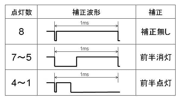
int adj[ 8 ] = { 1, 160, 280, 380, 500, 300, 200, 50 };
// 2-dimensional array of pixels:
byte pixels[ 16 ][ 8 ];
byte pd[ 2 ];
byte pb[ 2 ];
byte pc[ 2 ];
byte on_count;
byte line_count;
byte i;
int x = 1; // display next position
int y = 1;
int x0 = 1; // display last position
int y0 = 1;
int accxin[AVE]; // sensor signal averaging array
int accyin[AVE];
byte spt = 0; // averaging pointer
int accx; // acceleration
int accy;
int dx; // velocity
int dy;
int dotx; // moving distance ( calculation )
int doty;
// all output Hi-Z
void alloff( void ){
DDRD &= B00000001; // line 543210
DDRB &= B11100000; // line BA9876
DDRC &= B11110000; // line FEDC
}
// make data
void bitmake( byte n, byte a )
{
if ( a < 8 ){
pd[ n ] |= _BV( a );
}else if ( a < 14 ){
pb[ n ] |= _BV( a - 8 );
}else{
pc[ n ] |= _BV( a -14 );
}
pinMode( SYNC, OUTPUT );
}
// LED output control by Charlieplexing
void LED_output( void ){
digitalWrite( SYNC, HIGH ); // debug sync out
digitalWrite( SYNC, LOW );
alloff();
// pre-delay for adjust
if ( ( on_count >= 5 ) && ( on_count < 8 ) ){
delayMicroseconds( adj[ on_count ] );
}
// 1 line scan output
DDRD |= pd[ 1 ];
PORTD = pd[ 0 ];
DDRB |= pb[ 1 ];
PORTB = pb[ 0 ];
DDRC |= pc[ 1 ];
PORTC = pc[ 0 ];
// post-delay for adjust
if ( on_count < 5 ){
delayMicroseconds( adj[ on_count ] );
alloff();
}
// next line
line_count++;
if ( line_count >= 16 ){
line_count = 0;
}
// make next data
pd[ 0 ] = 0;
pb[ 0 ] = 0;
pc[ 0 ] = 0;
on_count = 0;
for ( i=0; i < 8; i++){
if ( pixels[ line_count ][ i ] ){
bitmake( 0, line[ line_count ][ i + 1 ] );
on_count++;
}
}
pd[ 1 ] = pd[ 0 ];
pb[ 1 ] = pb[ 0 ];
pc[ 1 ] = pc[ 0 ];
bitmake( 1, line[ line_count ][ 0 ] );
}
// get acceleration data
void get_acc( void ){
// averaging acceleration sensor signal
accxin[ spt ] = analogRead( AX );
accyin[ spt ] = analogRead( AY );
spt++;
if ( spt >= AVE ){
spt = 0;
}
accx = 0;
accy = 0;
for ( i=0; i < AVE; i++){
accx += ( accxin[ i ] - XZEROG );
accy += ( accyin[ i ] - YZEROG );
}
accx /= AVE;
accy /= AVE;
// integrating acceleration makes velocity
dx += accx;
dy += accy;
// integrating velocity makes moving distance
dotx += dx;
doty += dy;
// reflection ( reverse velocity )
// 0 < x < 15
if ( dotx >= MAG*15){
dotx = MAG*15 - 1;
dx = -( dx * RF1 ) / RF2;
}else if ( dotx < MAG ){
dotx = MAG;
dx = -( dx * RF1 ) / RF2;
}
// 0 < y < 7
if ( doty >= MAG*7){
doty = MAG*7 - 1;
dy = -( dy * RF1 ) / RF2;
}else if ( doty < MAG ){
doty = MAG;
dy = -( dy * RF1 ) / RF2;
}
// x = accx + 8; // test acceleration value
// y = accy + 4;
// x = dx / 16 + 8; // test velocity value
// y = dy / 16 + 4;
x = dotx / MAG;
y = doty / MAG;
// display limitter
if ( x > 14) {
x = 14;
}else if ( x < 1 ){
x = 1;
}
if ( y > 6) {
y = 6;
}else if (y < 1){
y = 1;
}
}
// next dot setting
void MovingDot( void ){
// turn off the last position
pixels[x0][y0] = 0;
pixels[x0+1][y0] = 0;
pixels[x0-1][y0] = 0;
pixels[x0][y0+1] = 0;
pixels[x0][y0-1] = 0;
// turn on the next position
pixels[x][y] = 1;
pixels[x+1][y] = 1;
pixels[x-1][y] = 1;
pixels[x][y+1] = 1;
pixels[x][y-1] = 1;
// store last position
x0 = x;
y0 = y;
}
// timer interrupt
void timerirq( void ){
LED_output();
if ( line_count == 15 ){
get_acc();
}
MovingDot();
}
void setup(){
alloff();
line_count = 0;
MsTimer2::set( 1, timerirq ); // 1ms interrupt setting
MsTimer2::start();
pinMode( SYNC, OUTPUT ); // for debug
}
void loop(){
}
/*
  ikkeiplexing ( Charlieplexing by ikkei )
  Use dual 8x8 dot matrix LED
  brightness adjustment
  edited by ikkei 2010.08.22
*/

#include <MsTimer2.h>

#define A1 6
#define A2 10
#define A3 17
#define A4 2
#define A5 14
#define A6 3
#define A7 9
#define A8 5
#define K1 1
#define K2 4
#define K3 15
#define K4 7
#define K5 16
#define K6 8
#define K7 11
#define K8 12
#define SYNC 13  // debug sync out

// line component
const byte line[ 16 ][ 9 ] = {
  { K1, A8, A7, A6, A5, A4, A3, A2, A1 },
  { K2, A8, A7, A6, A5, A4, A3, A2, A1 },
  { K3, A8, A7, A6, A5, A4, A3, A2, A1 },
  { K4, A8, A7, A6, A5, A4, A3, A2, A1 },
  { K5, A8, A7, A6, A5, A4, A3, A2, A1 },
  { K6, A8, A7, A6, A5, A4, A3, A2, A1 },
  { K7, A8, A7, A6, A5, A4, A3, A2, A1 },
  { K8, A8, A7, A6, A5, A4, A3, A2, A1 },
  { A1, K8, K7, K6, K5, K4, K3, K2, K1 },
  { A2, K8, K7, K6, K5, K4, K3, K2, K1 },
  { A3, K8, K7, K6, K5, K4, K3, K2, K1 },
  { A4, K8, K7, K6, K5, K4, K3, K2, K1 },
  { A5, K8, K7, K6, K5, K4, K3, K2, K1 },
  { A6, K8, K7, K6, K5, K4, K3, K2, K1 },
  { A7, K8, K7, K6, K5, K4, K3, K2, K1 },
  { A8, K8, K7, K6, K5, K4, K3, K2, K1 }
};

// parameter for adjust ( micro second )
int adj[ 8 ] = { 1, 160, 280, 380, 500, 300, 200, 50 };

// 2-dimensional array of pixels:
byte pixels[ 16 ][ 8 ] = {
  {0, 0, 0, 0, 0, 0, 0, 0},  // test pattern
  {1, 0, 0, 0, 0, 0, 0, 0},
  {1, 1, 1, 1, 1, 1, 1, 1},
  {1, 1, 0, 0, 0, 0, 0, 0},
  {1, 1, 1, 1, 1, 1, 1, 1},
  {1, 1, 1, 0, 0, 0, 0, 0},
  {1, 1, 1, 1, 1, 1, 1, 1},
  {1, 1, 1, 1, 0, 0, 0, 0},
  {1, 1, 1, 1, 1, 1, 1, 1},
  {1, 1, 1, 1, 1, 0, 0, 0},
  {1, 1, 1, 1, 1, 1, 1, 1},
  {1, 1, 1, 1, 1, 1, 0, 0},
  {1, 1, 1, 1, 1, 1, 1, 1},
  {1, 1, 1, 1, 1, 1, 1, 0},
  {1, 1, 1, 1, 1, 1, 1, 1},
  {0, 0, 0, 0, 0, 0, 0, 0},
};

byte pd[ 2 ];
byte pb[ 2 ];
byte pc[ 2 ];
byte on_count;
byte line_count;
byte i;

// all output Hi-Z
void alloff( void ){
  DDRD &= B00000001; // line 543210
  DDRB &= B11100000; // line BA9876
  DDRC &= B11110000; // line FEDC
}

// make data
void bitmake( byte n, byte a )
{
  if ( a < 8 ){
    pd[ n ] |= _BV( a );
  }else if ( a < 14 ){
    pb[ n ] |= _BV( a - 8 );
  }else{
    pc[ n ] |= _BV( a -14 );
  }
  pinMode( SYNC, OUTPUT );
}

// LED output control by Charlieplexing
void LED_digit( void ){
  digitalWrite( SYNC, HIGH );  // debug sync out
  digitalWrite( SYNC, LOW );
  alloff();

  // pre-delay for adjust
  if ( ( on_count >= 5 ) && ( on_count < 8 ) ){
    delayMicroseconds( adj[ on_count ] );
  }

  // 1 line scan output
  DDRD  |= pd[ 1 ];
  PORTD = pd[ 0 ];
  DDRB  |= pb[ 1 ];
  PORTB = pb[ 0 ];
  DDRC  |= pc[ 1 ];
  PORTC = pc[ 0 ];

  // post-delay for adjust
  if ( on_count < 5 ){
    delayMicroseconds( adj[ on_count ] );
    alloff();
  }

  // next line
  line_count++;
  if ( line_count >= 16 ){
    line_count = 0;
  }

  // make next data
  pd[ 0 ] = 0;
  pb[ 0 ] = 0;
  pc[ 0 ] = 0;
  on_count = 0;
  for ( i=0; i < 8; i++){
    if ( pixels[ line_count ][ i ] ){
      bitmake( 0, line[ line_count ][ i + 1 ] );
      on_count++;
    }
  }
  pd[ 1 ] = pd[ 0 ];
  pb[ 1 ] = pb[ 0 ];
  pc[ 1 ] = pc[ 0 ];
  bitmake( 1, line[ line_count ][ 0 ] );

}

void setup(){
  alloff();
  line_count = 0;
  MsTimer2::set( 1, LED_digit ); // 1ms interrupt setting
  MsTimer2::start();
  pinMode( SYNC, OUTPUT ); // for debug
}

void loop(){
}

</pre>