この週末は大阪でしたので、例によって日本橋へ行きました。
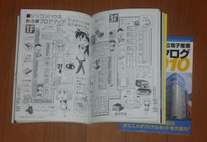
共立電子で、29日発売の「電子工作マニア2」をちょっと早めにゲットできました。
なるほど、共立電子のキットカタログが付いているから、早かったんですね。 
中には、共立電子の新店舗のフロアマップが紹介されていました。
/*
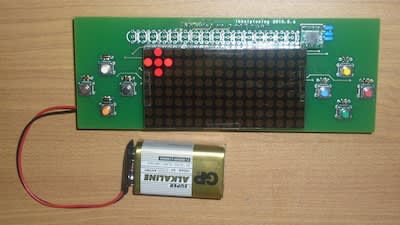
ikkeiplexing ( Charlieplexing by ikkei )
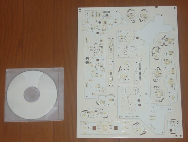
Use dual 8x8 dot matrix LED
Testing of switch inputs
edited by ikkei 2010.06.23
*/
#include <MsTimer2.h>
#define A1 6
#define A2 10
#define A3 17
#define A4 2
#define A5 14
#define A6 3
#define A7 9
#define A8 5
#define K1 1
#define K2 4
#define K3 15
#define K4 7
#define K5 16
#define K6 8
#define K7 11
#define K8 12
#define AX 4
#define AY 5
const byte SWcom1 = A1;
const byte SW1 = A5;
const byte SW2 = A6;
const byte SW3 = A7;
const byte SW4 = A8;
const byte SWcom2 = A2;
const byte SW5 = A5;
const byte SW6 = A6;
const byte SW7 = A7;
const byte SW8 = A8;
const byte LINE[ 16 ][ 9 ] = {
{ K1, A1, A2, A3, A4, A5, A6, A7, A8 },
{ K2, A1, A2, A3, A4, A5, A6, A7, A8 },
{ K3, A1, A2, A3, A4, A5, A6, A7, A8 },
{ K4, A1, A2, A3, A4, A5, A6, A7, A8 },
{ K5, A1, A2, A3, A4, A5, A6, A7, A8 },
{ K6, A1, A2, A3, A4, A5, A6, A7, A8 },
{ K7, A1, A2, A3, A4, A5, A6, A7, A8 },
{ K8, A1, A2, A3, A4, A5, A6, A7, A8 },
{ A1, K1, K2, K3, K4, K5, K6, K7, K8 },
{ A2, K1, K2, K3, K4, K5, K6, K7, K8 },
{ A3, K1, K2, K3, K4, K5, K6, K7, K8 },
{ A4, K1, K2, K3, K4, K5, K6, K7, K8 },
{ A5, K1, K2, K3, K4, K5, K6, K7, K8 },
{ A6, K1, K2, K3, K4, K5, K6, K7, K8 },
{ A7, K1, K2, K3, K4, K5, K6, K7, K8 },
{ A8, K1, K2, K3, K4, K5, K6, K7, K8 }};
// 2-dimensional array of pixels:
byte pixels[16][8];
byte count;
byte i;
byte common;
byte SW_data1;
byte SW_data2;
byte SW_data3;
byte SW_data4;
byte SW_data5;
byte SW_data6;
byte SW_data7;
byte SW_data8;
// all output Hi-Z
void alloff( void ){
for ( i=0; i < 16; i++){
pinMode( LINE[ i ][ 0 ], INPUT );
}
}
// LED output control by Charlieplexing
void LED_digit( void ){
alloff();
common = LINE[ count ][ 0 ];
pinMode( common , OUTPUT );
digitalWrite( common , LOW ); // common cathode LOW output
if ( common == SWcom1 ){ // input left 4 switches
digitalWrite(SW1, HIGH); // Pull Up resistor ON
digitalWrite(SW2, HIGH);
digitalWrite(SW3, HIGH);
digitalWrite(SW4, HIGH);
SW_data1 = digitalRead(SW1) ^ 0x01; // switch on L
SW_data2 = digitalRead(SW2) ^ 0x01;
SW_data3 = digitalRead(SW3) ^ 0x01;
SW_data4 = digitalRead(SW4) ^ 0x01;
}else if ( common == SWcom2 ){ // input right 4 switches
digitalWrite(SW5, HIGH); // Pull Up resistor ON
digitalWrite(SW6, HIGH);
digitalWrite(SW7, HIGH);
digitalWrite(SW8, HIGH);
SW_data5 = digitalRead(SW5) ^ 0x01; // switch on L
SW_data6 = digitalRead(SW6) ^ 0x01;
SW_data7 = digitalRead(SW7) ^ 0x01;
SW_data8 = digitalRead(SW8) ^ 0x01;
}
// 1 line output
for ( i=0; i < 8; i++){
if ( pixels[ count ][i] ){
pinMode( LINE[ count ][ 8-i ], OUTPUT);
digitalWrite( LINE[ count ][ 8-i ], HIGH); // turn on LED anode HIGH output
}
}
count++;
if ( count > 15 ){
count = 0;
pixels[ 4][7] = SW_data1;
pixels[ 1][4] = SW_data2;
pixels[ 7][4] = SW_data3;
pixels[ 4][1] = SW_data4;
pixels[12][7] = SW_data5;
pixels[ 9][4] = SW_data6;
pixels[15][4] = SW_data7;
pixels[12][1] = SW_data8;
}
}
void setup(){
alloff();
count = 0;
MsTimer2::set( 1, LED_digit); // 1ms interrupt setting
MsTimer2::start();
pixels[ 4][4] = 1;
pixels[ 5][4] = 1;
pixels[ 3][4] = 1;
pixels[ 4][5] = 1;
pixels[ 4][3] = 1;
pixels[12][4] = 1;
pixels[13][4] = 1;
pixels[11][4] = 1;
pixels[12][5] = 1;
pixels[12][3] = 1;
}
void loop(){
}

/*
  ikkeiplexing ( Charlieplexing by ikkei )
  Use dual 8x8 dot matrix LED
  Moving Dot
  edited by ikkei 2010.06.22
*/

#include

#define A1 6
#define A2 10
#define A3 17
#define A4 2
#define A5 14
#define A6 3
#define A7 9
#define A8 5
#define K1 1
#define K2 4
#define K3 15
#define K4 7
#define K5 16
#define K6 8
#define K7 11
#define K8 12
#define AX 4
#define AY 5
#define AVE 16 // averaging times
#define XZEROG 518  // adjust offset value of zero G x-axis
#define YZEROG 545  // adjust offset value of zero G y-axis
#define RF1 3  // reflection rate RF1/RF2
#define RF2 4
#define MAG 1024  // magnify rate

const byte LINE[ 16 ][ 9 ] = {
{ K1, A1, A2, A3, A4, A5, A6, A7, A8 },
{ K2, A1, A2, A3, A4, A5, A6, A7, A8 },
{ K3, A1, A2, A3, A4, A5, A6, A7, A8 },
{ K4, A1, A2, A3, A4, A5, A6, A7, A8 },
{ K5, A1, A2, A3, A4, A5, A6, A7, A8 },
{ K6, A1, A2, A3, A4, A5, A6, A7, A8 },
{ K7, A1, A2, A3, A4, A5, A6, A7, A8 },
{ K8, A1, A2, A3, A4, A5, A6, A7, A8 },
{ A1, K1, K2, K3, K4, K5, K6, K7, K8 },
{ A2, K1, K2, K3, K4, K5, K6, K7, K8 },
{ A3, K1, K2, K3, K4, K5, K6, K7, K8 },
{ A4, K1, K2, K3, K4, K5, K6, K7, K8 },
{ A5, K1, K2, K3, K4, K5, K6, K7, K8 },
{ A6, K1, K2, K3, K4, K5, K6, K7, K8 },
{ A7, K1, K2, K3, K4, K5, K6, K7, K8 },
{ A8, K1, K2, K3, K4, K5, K6, K7, K8 }};

// 2-dimensional array of pixels:
int pixels[16][8];

int count;
int i;
int x = 1;  // display next position
int y = 1;
int x0 = 1;  // display last position
int y0 = 1;
int accxin[AVE];  // sensor signal averaging array
int accyin[AVE];
byte spt = 0;  // averaging pointer
int accx;  // acceleration
int accy;
int dx;  // velocity
int dy;
int dotx;  // moving distance ( calculation )
int doty;

void get_acc( void ){
  // averaging acceleration sensor signal
  accxin[ spt ] = analogRead( AX );
  accyin[ spt ] = analogRead( AY );
  spt++;
  if ( spt >= AVE ){
    spt = 0;
  }
  accx = 0;
  accy = 0;
  for ( i=0; i < AVE; i++){
    accx += ( accxin[ i ] - XZEROG );
    accy += ( accyin[ i ] - YZEROG );
  }
  accx /= AVE;
  accy /= AVE;

  // integrating acceleration makes velocity
  dx += accx;
  dy += accy;

  // integrating velocity makes moving distance
  dotx += dx;
  doty += dy;

  // reflection ( reverse velocity )
  // 0 < x < 15
  if ( dotx >= MAG*15){
    dotx = MAG*15 - 1;
    dx = -( dx * RF1 ) / RF2;
  }else if ( dotx < MAG ){
    dotx = MAG;
    dx = -( dx * RF1 ) / RF2;
  }
  // 0 < y < 7
  if ( doty >= MAG*7){
    doty = MAG*7 - 1;
    dy = -( dy * RF1 ) / RF2;
  }else if ( doty < MAG ){
    doty = MAG;
    dy = -( dy * RF1 ) / RF2;
  }

//  x = accx + 8;    // test acceleration value
//  y = accy + 4;
//  x = dx / 16 + 8;  // test velocity value
//  y = dy / 16 + 4;
  x = dotx / MAG;
  y = doty / MAG;

  // display limitter
  if ( x > 14) {
    x = 14;
  }else if ( x < 1 ){
    x = 1;
  }
  if ( y > 6) {
    y = 6;
  }else if (y < 1){
    y = 1;
  }
}

// all output Hi-Z
void alloff( void ){
  for ( i=0; i < 16; i++){
    pinMode( LINE[ i ][ 0 ], INPUT );
  }
}

// LED output control by Charlieplexing
void LED_digit( void ){
  alloff();
  pinMode( LINE[ count ][ 0 ], OUTPUT);
  digitalWrite( LINE[ count ][ 0 ], LOW);  // common cathode LOW output
  for ( i=0; i < 8; i++){
    if ( pixels[ count ][i] ){
      pinMode( LINE[ count ][ 8-i ], OUTPUT);
      digitalWrite( LINE[ count ][ 8-i ], HIGH);  // turn on LED anode HIGH output
    }
  }
  count++;
  if ( count > 15 ){
    count = 0;
    get_acc();  // get acceleration and calculate next position
  }

  // turn off the last position
  pixels[x0][y0] = 0;
  pixels[x0+1][y0] = 0;
  pixels[x0-1][y0] = 0;
  pixels[x0][y0+1] = 0;
  pixels[x0][y0-1] = 0;

  // turn on the next position
  pixels[x][y] = 1;
  pixels[x+1][y] = 1;
  pixels[x-1][y] = 1;
  pixels[x][y+1] = 1;
  pixels[x][y-1] = 1;

  // store last position
  x0 = x;
  y0 = y;
}

void setup(){
  alloff();
  count = 0;
  MsTimer2::set( 1, LED_digit); // 1ms interrupt setting
  MsTimer2::start();
}

void loop(){
}