『低音がほしい!! vol.9』の続きです。
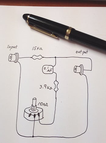
連続可変型の低域増強アダプターの回路図はこんな感じです。

回路図が判り難いとのご意見をいただきましたので
今回は回路図について解説します。
input、outputとあるのはピンジャックです。

同心円のセンターがホット、周囲がグランドで
これは実物と同じです。
ボリュームは回転させることで値が変化する抵抗です。
回路図では『抵抗』+『矢印』で表示します。
この回路図を実際の部品に置き換えてみるとこうなります。
続く・・・
(製作が困難な場合もあるかとおもいますので、低域増強アダプターははccmで販売もしています)
I want a low frequency !! vol.10
It is a continuation of "I want a low frequency !! vol.9"
It is a circuit diagram of a variable bass adapter.
There was an opinion that a circuit diagram is unclear.
A circuit diagram is explained.
input and output are RCA jacks.
The center of a concentric circle is a hot terminal.
The circumference is Grand terminal.
This is the same as thing.
Rheostat is the resistor from which a value changes by making it rotate.
It expresses as a circuit diagram by the "resistor" + "arrow."
A circuit diagram is transposed to actual parts.
To be continued.