Vias can be used to electrically connect metal lines above the vias to metal lines below the vias. Vias are typically formed by a lithographic process.
ビアは、ビアの上方にある金属ラインをビアの下方にある金属ラインに電気的に接続するために用いられ得る。ビアは通常、リソグラフィープロセスで形成される。
Representatively, a photoresist layer may be spin coated above a dielectric layer, the photoresist layer may be exposed to patterned actinic radiation through a patterned mask,
代表例を挙げると、フォトレジスト層を誘電体層の上方にスピンコーティングで形成し、パターニングされたマスクを介してフォトレジスト層をパターニングされた化学線で露光するとしてよい。
and then the exposed layer may be developed in order to form an opening in the photoresist layer.
この後、露光されたフォトレジスト層を現像して、フォトレジスト層に開口を形成するとしてよい。
Next, an opening for the via may be etched in the dielectric layer by using the opening in the photoresist layer as an etch mask.
次に、フォトレジスト層に形成された開口をエッチングマスクとして用いて、誘電体層にビア用の開口をエッチングで形成するとしてよい。
This opening is referred to as a via opening. Finally, the via opening may be filled with one or more metals or other conductive materials to form the via.
この開口をビア開口と呼ぶ。最後に、ビア開口を1あるいは複数の金属または他の導電性材料で充填して、ビアを形成するとしてよい。
[00114] Figure 21B illustrates a cross-sectional view of a stack 2150 of metallization layers 2152 in an integrated circuit based on metal line layouts of the type illustrated in Figure 21 A, in accordance with an embodiment of the present invention.
図21Bは、本発明の一実施形態に応じた、図21Aに図示したタイプの金属ラインレイアウトに基づく集積回路内の複数のメタライゼーション層2152で構成される積層体2150を示す断面図である。
Referring to Figure 21B, in an exemplary embodiment, a metal cross- section for an interconnect stack 2150 is derived from a single BAA array for the lower eight matched metal layers 2154, 2156, 2158, 2160, 2162, 2164, 2166 and 2168.
図21Bを参照すると、一実施形態例において、インターコネクト積層体2150の金属断面は、下層の8個の一致する金属層2154、2156、2158、2160、2162、2164、2166および2168について一のBAAアレイを用いて得られる。
It is to be appreciated that upper thicker/wider metal lines 2170 and 2172 would not be made with the single BAA.
上層のより厚み/幅の大きい金属ライン2170および2172はこの一のBAAを用いて形成されるものではないと考えられたい。
Via locations 2174 are depicted as connecting the lower eight matched metal layers 2154, 2156, 2158, 2160, 2162, 2164, 2166 and 2168.
ビア位置2174は、下層の8個の一致する金属層2154、2156、2158、2160、2162、2164、2166および2168を接続させるものとして図示されている。
[00116] In an embodiment, a beam aperture array is implemented to solve throughput of an ebeam machine while also enabling minimum wire pitch.
一実施形態において、ワイヤピッチを最小限に抑えることも可能としつつ電子ビーム機械のスループットの問題を解決するべく、ビームアパーチャアレイを実装する。
As described above, with no stagger, the problem of edge placement error (EPE) means that a minimum pitch that is twice the wire width cannot be cut
上述したように、スタッガード構成を持たない場合、エッジ配置エラー(EPE)の問題とは、ワイヤ幅の2倍である最小ピッチはカットできないことを意味する。
since there is no possibility of stacking vertically in single stack.
これは、一の積層体において縦方向に積層する可能性はないためである。
Embodiments described below extend the staggered BAA concept to permit three separate pitches to be exposed on a wafer,
後述する実施形態は、スタッガードBAAの概念を拡張して、3つの別個のピッチをウェハ上で露光させる。
either through three passes, or by illuminating/controlling all three beam aperture arrays simultaneously in a single pass.
この際、3回通過させて行うとしてもよいし、または、3つのビームアパーチャアレイ全てを同時に一回で通過させて露光/制御するとしてもよい。
The latter approach may be preferable for achieving the best throughput.
最良スループットを実現するためには後者の方法が好ましいとしてよい。
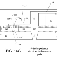
[0163] As part of operation 1415, one or more electrical vias may be formed between the various layers of the laminate structure.
動作1415の一部として、積層構造体の様々な層間に、1つ以上の電気ビアを形成することができる。
In some cases, electrical vias are formed through the compressible layer to connect circuit layers that are disposed on opposite sides of the compressible layer.
一部の場合には、電気ビアは、圧縮性層の両側に配置される回路層を接続するために、圧縮性層を貫通して形成される。
The vias may be formed by, for example, the addition of conductive pillar elements that electrically connect the conductive layers of different circuit layers.
これらのビアは、例えば、異なる回路層の導電層を電気的に接続する、導電性ピラー素子の追加によって、形成することができる。
[0159] In operation 1410, a second circuit layer is obtained. In this example, the second circuit layer also comprises at least a second flexible conductive layer and a second flexible dielectric layer.
動作1410では、第2の回路層が得られる。この実施例では、第2の回路層もまた、少なくとも、第2の可撓性導電層及び第2の可撓性誘電層を備える。
With reference to FIG. 13, the second circuit layer may also include one of either circuit layer pairs 121 1 , 1221 or 1222, 1212 (that is also separated from the first circuit layer by the intermediate compressible layer 1230).
図13を参照すると、第2の回路層もまた、回路層の対1211、1221、又は回路層の対1222、1212のいずれかのうちの一方(また中間の圧縮性層1230によって、第1の回路層から隔てられているもの)を含み得る。
As described above, the first circuit layer may be obtained by forming the first conductive layer on the first dielectric layer by laminating a metal foil or depositing a conductive material onto a surface of the dielectric layer.
上述のように、第1の回路層は、誘電層の表面上に、金属箔を積層するか、又は導電材料を堆積させることによって、第1の誘電層上に第1の導電層を形成することによって得ることができる。
The second circuit layer may also be pre-manufactured as a sheet or die-cut component.
第2の回路層もまた、シート又は打ち抜き構成要素として、予備製造することができる。
[0160] In operation 1415, a laminate structure is formed. In particular, a laminate structure is formed such that the compressible layer is disposed between the first and second circuit layers.
【0139】
動作1415では、積層構造体が形成される。具体的には、第1の回路層と第2の回路層との間に、圧縮性層が配置されるように、積層構造体が形成される。
With reference to FIG. 13, an exemplary laminate structure includes the four circuit layers 121 1 , 1221 , 1222, 1212 and the compressible layer 1230.
図13を参照すると、例示的な積層構造体は、4つの回路層1211、1221、1222、1212、及び圧縮性層1230を含む。
In many cases, other layers are formed as part of the laminate structure.
多くの場合には、この積層構造体の一部として、他の層が形成される。
For example, additional circuit layers, adhesive layers, and coatings may be formed as part of the laminate structure.
例えば、追加的な回路層、接着剤層、及びコーティングを、積層構造体の一部として形成することができる。
In particular, an adhesive layer is typically used to bond the intermediate compressible layer with the other, adjacent components of the laminate structure.
具体的には、接着剤層は、典型的には、中間の圧縮性層を、積層構造体の他の隣接する構成要素と接合させるために使用される。
It is not necessary that either the first or second circuit layers (obtained in operations 1405 and 1410) be immediately adjacent or bonded directly to the compressible layer.
(動作1405及び動作1410で得られた)第1の回路層又は第2の回路層が、圧縮性層に直接隣接するか、若しくは直接接合されることは必須ではない。
[0161] Operation 1415 may be performed by, for example, placing pressure sensitive adhesive (PSA) layers between the components of the laminate structure.
【0140】
動作1415は、例えば、積層構造体の構成要素間に、感圧接着剤(PSA)層を定置することによって、実行することができる。
The laminate may then be subjected to a pressing operation to bond the layers.
次いで、この積層体に押圧動作を施すことにより、それらの層を接合することができる。
In some cases, heat or other curing techniques may be employed to bond the layers together.
一部の場合には、それらの層を一体に接合するために、熱又は他の硬化技術を採用することができる。
In some embodiments, the PSA may be applied, all layers bonded, and then the structure die cut to its final form.
一部の実施形態では、PSAを適用して全ての層を接合し、次いで構造体を最終的な形態にダイカットしてもよい。
[0002] Electronic devices may be connected using cables and connectors.
[0002]電子装置は、ケーブルおよびコネクタを使用して接続されてもよい。
An example of a popular serial data interface is THUNDERBOLT, capable of a transfer speed of lOGbit/ <'>second and available using a copper cable and a MINI DISPLAYPQRT connector.
よく知られているシリアルデータインタフェースの一例は、10ギガビット/秒の転送速度が可能であるとともに銅ケーブルとMINI DISPLAYPORTコネクタとを使用して利用できるTHUNDERBOLTである。
[0129] The method further includes stacking the plurality of stackable blades to form an interconnected stack (3614).
[0129]方法は、相互接続される積層体を形成するために複数の積層可能なブレードを積層するステップ(3614)を更に含む。
Each of the plurality of stackable blades are coupled using the standard physical interface.
複数の積層可能なブレードのそれぞれは、標準的な物理インタフェースを使用して結合される。
In an embodiment, the standard physical interface comprises one or more magnets disposed on a coupling face and a plurality of terminals disposed on the coupling face.
一実施形態において、標準的な物理インタフェースは、結合面上に配置される1つ以上の磁石と、結合面上に配置される複数の端子とを備える。
The periphery of the one or more magnets and the plurality of terminals define a coupling area and the peripheral area of one or more of the plurality of stackable blades is greater than and independent of the coupling area.
1つ以上の磁石および複数の端子の外周は結合領域を画定し、また、複数の積層可能なブレードのうちの1つ以上の外周領域は、結合領域よりも大きいとともに結合領域から独立している。
In a particular embodiment, the standard physical interface is characterized by a bisector,
特定の実施形態では、標準的な物理インタフェースが二等分線によって特徴付けられ、
the one or more magnets comprise at least a pair of magnets,
1つ以上の磁石が少なくとも一対の磁石を備え、
each magnet of the at least one pair of magnets being positioned an equal distance from the bisector,
少なくとも1つの対の磁石の各磁石が二等分線から等距離に配置され、
and the plurality of terminals are arrayed in pairs. Each terminal of each pair is positioned an equal distance from the bisector.
また、複数の端子が対を成して配列される。各対のそれぞれの端子は、二等分線から等距離に配置される。