和英特許翻訳メモ

便利そうな表現、疑問、謎、その他メモ書き。思いつきで書いてます。
拾った用例は必ずしも典型例、模範例ではありません。

合成インピーダンス

2021-02-28 13:16:25 | 英語特許散策

EP2686953
[0036] The compensated carrier phase shift φC-COMPis the negative of the phase shift provided by the carrier input network 34 (φC-IP) minus a carrier phase offset φC-PO, wherein φC-COMP= -φC-IP- φC-PO.
【0037】
  [0048]  補償済キャリア位相シフトφC-COMPは、キャリア入力回路網34により与えられる位相シフト(φC-IP)を負にしたものから、キャリア位相オフセットφC-POを減算したものであり、φC-COMP=-φC-IP-φC-POとなる。

In this example, the phase shift provided by the carrier input network 34 (φC-IP) is +45°. The carrier phase offset φC-POcorresponds to the reactive component of the impedance presented to the output of the carrier power amplifier circuitry 36 at the intended operating frequency range or ranges.
この例では、キャリア入力回路網34により与えられる位相シフト(φC-IP)は+45度である。キャリア位相オフセットφC-POは、意図された動作周波数の範囲(1以上の範囲)でキャリア電力増幅器回路36の出力へ与えられるインピーダンスの無効成分に対応する。

This impedance is effectively the composite impedance provided by the carrier output network 38, the peaking path, and the transformer 42 at the intended operating frequency range or ranges.
このインピーダンスは、実際には、意図された動作周波数の範囲(1以上の範囲)でキャリア出力回路網38、ピーキング経路、および変成器42により与えられる合成インピーダンスである。

The goal is to have a substantially real impedance (pure resistive) presented to the output of the carrier power amplifier circuitry 36 at the intended operating frequency range or ranges.
目的は、意図された動作周波数の範囲(1以上の範囲)でキャリア電力増幅器回路36の出力へ実質的な実インピーダンス(純粋な抵抗)を与えることである。

WO2017139316
[00030] Consequently, in contrast to such conventional approaches, and in accordance with an embodiment of the disclosure,
【0028】
  したがって、そのような従来アプローチとは対照的に、本開示の一実施形態によれば、

the per unit distance "d" of the fault at location 315 can be determined by interpreting the combination of the series capacitor 105 and the series capacitor protection element 115 as a collective impedance representing the combined impedance of the series capacitor 105 and the series capacitor protection element 115 when a fault occurs in the series-compensated power transmission line system 100.
位置315における障害の単位当たりの距離「d」は、直列コンデンサ105と直列コンデンサ保護要素115との組合せを、直列補償送電線システム100に障害が発生した場合の直列コンデンサ105と直列コンデンサ保護要素115との合成インピーダンスを表す集合インピーダンスとして解釈することによって判定することができる。

WO2016040457
[0209] In addition, a variable control load Zc is coupled in parallel with the electrical load 315.
【0183】
  さらに、可変制御負荷Zは、電気的負荷315に並列に結合されている。

The com switch 2210 may include, for example, a manually controlled switch, a solid-state device, a switch controlled by a computing device, or other apparatus configured to open and close a circuit switch.
comスイッチ2210は、たとえば、手動制御スイッチ、固体デバイス、コンピューティングデバイスによって制御されるスイッチ、又は回路スイッチを開閉するように構成された他の装置を含んでいてもよい。

In this embodiment, the combined impedance of the variable control load Zc would be the combined impedances of Zi and Z2 when the com switch 2210 is closed, and only the impedance of Zi when the com switch 2210 is opened.
本実施形態では、comスイッチ2210が閉じている場合、可変制御負荷Z合成インピーダンスはZとZを合わせたインピーダンスであり、comスイッチ2210が開いている場合は、Zのインピーダンスのみである。

By modulating the state of the com switch 2210 between opened and closed, an aggregate load presented by the variable control load Zc and the electric load 315 is modulated accordingly due to the varying impedance of the variable control load Zc.
開いた状態と閉じた状態の間でcomスイッチ2210を変調することによって、可変制御負荷Zと電気負荷315によって示される総負荷は、可変制御負荷Zの変動するインピーダンスにより調節される。

In an alternative embodiment, the impedance Zi may be omitted, such that the aggregate load coupled to the tuned resonator 306 varies between the electrical load 315 alone (the com switch leaves the pathway through the impedance Zi open) and the impedance Z2 in parallel with the electrical load 315.
代替的実施形態では、同調共振器306に結合された総負荷が、電気的負荷315のみ(comスイッチはインピーダンスZを通る経路を開いたままにする)と、電気的負荷315に並列であるインピーダンスZとの間で変化するよう、インピーダンスZを省略してもよい。

By varying the impedance in parallel with the electrical load 315, the com switch modulates the aggregate electric load coupled to the linear probe 303. In addition, there may be many other ways of modulating a load as can be appreciated.
電気的負荷315と並列であるインピーダンスを変化させることによって、comスイッチは、線形プローブ303に結合された総電気的負荷を変調する。さらに、理解できるように、負荷を変調する多くの他の方法があってもよい。

コメント
  • Twitterでシェアする
  • Facebookでシェアする
  • はてなブックマークに追加する
  • LINEでシェアする

正弦波状に変化

2021-02-27 22:09:25 | 英語特許散策

EP3258841
[0051] If, however, the analyzer 118 is determining the DC and AC magnitudes using a recursive calculation, then there are new DC and AC magnitudes calculated with each incoming sample (data point).
【0052】
  しかしながら、分析器118が再帰的計算を使用してDC及びACの振幅を決定している場合には、各入力サンプル(データ点)で計算される新たなDC及びACの振幅が存在する。

In such a circumstance, the analyzer 118 may be configured such that when the analyzer 118 determines that a change has occurred in the DC and AC magnitudes, the analyzer 118 collects data on a plurality of successive AC magnitudes.
このような状況では、分析器118は、分析器118がDC及びAC振幅において変化が生じたことを決定すると、分析器118が複数の連続するAC振幅のデータを収集するように構成できる。

If the jaws of the instrument 106 have tissue between them, then light intensity absorbed may vary only to a small degree and the magnitudes should not change much.
器具106のジョー部がそれらの間に組織を有する場合には、吸収される光の強度はわずかな程度でしか変化しないことがあり、振幅はあまり変化していないはずである。

Because the AC magnitude is proportional to the change in the observed values, it will also experience a small increase in value with the following incoming samples.
AC振幅は観察される値の変化に比例するため、次の入力サンプルで値がわずかに増加する。

If there is a blood vessel, or more particularly an edge of a blood vessel, at the distalmost edge of the jaws, then the magnitudes will change in a sinusoidal fashion and the AC magnitudes should see a drastic change with the next incoming sample (data point).
血管又はより具体的には血管の辺縁がジョー部の遠位端にある場合には、振幅は正弦波状に変化し、AC振幅は次の入力サンプル(データ点)で大幅な変化を見るはずである。

WO2019083636
[0034] With respect to the controlling of the three-phase currents, voltages, and magnetic fluxes in the PM electrical machine,
【0024】
  PM電気機械の三相電流、電圧、および磁束の制御に関して、

it is known that a dqO (or dqz) transformation is a common tool in electrical machines analysis -
dq0(または、dqz)変換が電気機械の分析における一般的なツールであることが知られており、

with the dqO transformation being a base-transformation that transforms sinusoidally varying signals in the machine (i.e., the currents, voltages, magnetic fluxes) into constant values, thus making analysis much easier to perform.
dq0変換が、機械において正弦波状に変化する信号(すなわち、電流、電圧、磁束)を一定値に変換することで、分析の実行をはるかに容易にする基本変換である。

For a three-phase electrical machine, the transformation is described by:
三相電気機械について、変換は

cos( Θ) cos( 0 - ^) cos( 0 + ^)i-dqc Piabc [Eqn. 1],


000003
    (式1)
  によって表され、

where P is the transformation matrix employed and 9 the parameter of such transformation,
ここで、Pは採用された変換行列であり、θはそのような変換のパラメータであり、

usually assumed equal to the relative electrical position between stator and rotor reference points,
通常は固定子おおび回転子の基準点の間の相対的な電気的位置に等しいと仮定され、

with one common choice assuming 9 = 0 for the stator-rotor relative position corresponding to the peak of the fundamental flux linkage in one of the phases of the machines.
1つの一般的な選択肢は、機械の相のうちの1つにおける基本的な磁束鎖交のピークに対応する固定子-回転子の相対位置についてθ=0とする。

US2003104761
[0072] However, some of the intensity measurements for sampling zones that are partially below the retaining ring will still provide useful data.
【0057】
  しかし、支持リングの下にある部分的な、サンプリング領域についての強度測定値のいくつかは、なお有用なデータを提供するであろう。

Since the retaining ring has a generally constant reflectivity, whereas the substrate has a reflectivity that varies sinusoidally as a function of time, the intensity measurements from sampling zones that overlap the substrate edge will still exhibit sinusoidal behavior, although with a reduced amplitude and an increased DC offset.
支持リングは略一定の反射率を有し、それに対して基板は時間の関数として正弦波状に変化する反射率を有するので、基板の縁を覆うサンプリング領域からの強度測定値は、振幅が減少し、DCオフセットが増大するけれども、なお正弦波状の振る舞いを示す。

The selection of the radial ranges that are excluded depend on the wafer diameter, platen speed and sampling rate.
除外される半径方向幅の選択は、ウエハ直径、プラテン速度およびサンプリングレートに依存する。

For example, for a sampling period of 25 millisecond and a platen rotation rate of 63 rmp, the sampling zones within 12 mm of the edge of a 200 mm substrate are not used in the thickness calculation.
例えば、25ミリ秒のサンプリング周期と63rpmのプラテン回転速度に対して、200mmの基板の縁の12mm以内のサンプリング領域は厚さ計算に用いられない。

コメント
  • Twitterでシェアする
  • Facebookでシェアする
  • はてなブックマークに追加する
  • LINEでシェアする

XY座標系

2021-02-27 21:58:04 | 英語特許散策

EP3745118
[0041] FIG. 6C is a diagram showing a light ray which first propagates from point P0 radially inward along a path 46 perpendicular to the Z-axis, is reflected 90 degrees by the conical mirror, and then propagates upward along a path 48 until the light ray impinges on the image sensor, thus producing the image point P1.
【0042】
  図6Cは、最初に点P0からZ軸に垂直な経路46に沿って半径方向内向きに伝播し、円錐ミラーによって90度反射され、次いで、光線が画像センサに衝突するまで経路48に沿って上向きに伝播し、結果として像点Pを生成する光線を示している。

As best seen in FIG. 6C , the maximum radius of the conical mirror 8 is equal to R0, while the distance from the Z-axis to the point where the light ray impinged on the conical mirror 8 is equal to r.
図6Cに最もよく示されているように、円錐ミラー8の最大半径はRに等しく、Z軸から光線が円錐ミラー8に衝突した点までの距離はrに等しい

The angle between the X-axis and a vector connecting the origin of the X-Y coordinate system(*初出で定冠詞)of the image sensor to the image point P1 is indicated by θ in FIG. 6B .
X軸と、画像センサのXY座標系の原点と像点Pとをつなぐベクトルとの間の角度は、図6Bでθによって示されている。

WO2009020726
[0034] FIG. 4 depicts a schematic of a display region 205 divided into multiple regions.
【0028】
  図4は、複数の領域に分割された表示領域205の概略図を示している。

In some implementations, the display region 205 can be rectangular in shape. An XY coordinate system(*不定冠詞)can be assigned to the display region 205
一実施例では、表示領域205は矩形の形状とすることができる。XY座標系を表示領域205に割り当てることができ、

wherein a direction(*不定冠詞)from the left edge of the display region 205 to the right edge 205 can correspond to a positive X direction and
表示領域205の左端から右端205の方向は、正のX方向に対応することができ、

a direction from the top edge of the display region 205 to the bottom edge of the display region 205 can correspond to a positive Y direction.
表示領域205の上端から表示領域205の下端の方向は、正のY方向に対応することができる。

コメント
  • Twitterでシェアする
  • Facebookでシェアする
  • はてなブックマークに追加する
  • LINEでシェアする

架台、台座

2021-02-27 12:09:59 | 英語特許散策

WO2005079468
Thus, it is a long felt need in the field of floor cleaning or treatment to provide a device that allows the operator to ride thereon, and which is adapted to be used in small areas and/or around tight corners.
【0010】
  このように、オペレータが乗ることができ、狭い領域及び/又は窮屈なコーナ廻りで使用されるに適した装置を提供することは、床の清掃もしくは処理の現場では、長い間感じられている要望である。

The following disclosure describes an improved floor cleaning and treatment device that is adapted for use in small areas that includes a platform adapted to support the operator to ensure optimum floor cleaning or treatment.
以下の開示は、狭い領域での使用に適合し、オペレータを支持するのに適合した台座(プラットホーム:platform)を有して、最適な床の清掃又は処理を確かなものとする、改良された床の清掃および処理装置を記載している。

SUMMARY OF THE INVENTION
It is one aspect of the present invention to provide a floor treatment apparatus that is easyto maneuver.
【課題を解決するための手段】
【0011】
  操縦することが容易な床処理装置を提供することは、本発明の一面である。

More specifically, one embodiment of the present invention is constructed of a chassis section that includes an enclosure that houses at least a portion of the internal components of the treatment device and a location for installation of devices that are used during cleaning operations.
より具体的に言えば、本発明の1つの実施形態は、少なくとも処理デバイスの内部部品の部分と清掃作業中に用いられるデバイスの据え付けのための場所を収容する囲い(エンクロージャ:enclosure)を含む架台(シャーシ:chassis)部で構成されている。

In addition, one embodiment of the present invention provides a standing, leaning or sitting location for the operator.
更に、本発明の1つの実施形態は、オペレータのために、立つ、もたれる或いは座る場所を提供する。

Another embodiment of the present invention is equipped with a powered steering device that allows for greater maneuverability in areas with tight corners, thereby ensuring that more of the flooring surface is treated without having to perform pre or post treatment operations.
本発明の今一つの実施形態は、窮屈なコーナ部がある領域でも非常に高い操縦性を許容する、動力が付与される操舵(ステアリング)装置を備えており、それにより、事前または事後の処理作業を要することなく、より広範な床張り表面が処理される。

More specifically, one embodiment of the present invention is equipped with a self-propelled wheel and an easy to use steering device to provide increased maneuverability around obstacles. One embodiment of the present invention employs at least one wheel that provides thrust and/or steering capability.
特に、本発明の1つの実施形態は、障害物の廻りでのより高い操縦性を与えるために、自走式の車輪と使用が簡単なステアリング装置を備えている。本発明の1つの実施形態は、推進および/または操舵機能をもたらす少なくとも1つの車輪を用いている。

Yet another embodiment of the present invention employs wheels that are substantially centered under the chassis such that the entire apparatus is generally capable of 360 rotation without substantially traversing in any other direction, thus allowing it to treat tight corners of a surface.
本発明の更に他の実施形態は、シャーシの下側で実質的に中央に置かれた車輪を用いており、その結果、装置全体が、他の如何なる方向においても実質的に動き回ることなく、全体として360度回転することができ、従って、表面の窮屈なコーナ部を処理できるようにしている。

It is another aspect of the present invention to provide a cleaning apparatus that is cost effective to manufacture. Various aspects of the invention shall now be described in more detail.
製造するのに費用に対し効率が良い清掃装置を提供することは、本発明の他の一面である。本発明の様々の一面を、より詳しく説明する。

WO2016014138
[0029] The substrate support assembly 126 generally includes at least a substrate support 132. The substrate support 132 may be a vacuum chuck, an electrostatic chuck, a susceptor, or other workpiece support surface.
【0018】
  基板支持アセンブリ126は、大略的に、少なくとも1つの基板支持体132を含んでいる。基板支持体132は、真空チャック、静電チャック、サセプタ、又は他のワークピース支持面であってもよい。

In the embodiment of Figure 1 , the substrate support 132 is an electrostatic chuck and will be described hereinafter as the electrostatic chuck 132. The substrate support assembly 126 may additionally include a heater assembly 170.
図1の実施形態において、基板支持体132は静電チャックであり、以下に静電チャック132として説明する。基板支持アセンブリ126はさらに、ヒータアセンブリ170を含んでいてもよい。

The substrate support assembly 126 may also include a cooling base 130. The cooling base may alternately be separate from the substrate support assembly 126. The substrate support assembly 126 may be removably coupled to a support pedestal 125.
基板支持アセンブリ126はまた、クーリングベース130も含んでいてもよい。あるいは、クーリングベースは基板支持アセンブリ126とは別個に設けられていてもよい。基板支持アセンブリ126は、支持架台125に取外し可能に結合されていてもよい。

The support pedestal 125, which may include a pedestal base 128 and a facility plate 180, is mounted to the chamber body 102.
支持架台125は、台座128及びファシリティプレート180を含んでいてもよく、チャンバ本体102に取り付けられる。

The substrate support assembly 126 may be periodically removed from the support pedestal 125 to allow for refurbishment of one or more components of the substrate support assembly 126.
基板支持アセンブリ126は、定期的に支持架台125から取外されて基板支持アセンブリ126の1つ以上の構成要素の改修が可能になるようにしてもよい。

WO2014179522
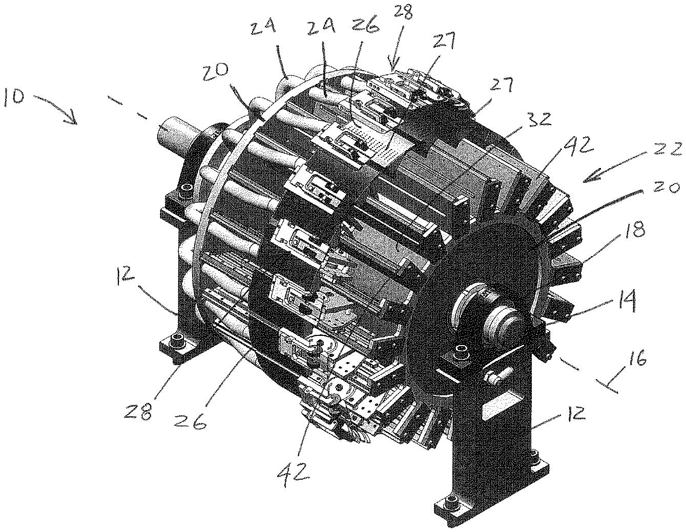
In an embodiment, referring to Figs. 1-6, an example cutting apparatus 10 is disclosed.
【0015】
  一実施形態では、図1~図6を参照して、切断装置10の例が開示される。

The cutting apparatus 10 may take the form a rotating device or other suitable device.
切断装置10は、回転デバイス又は他の好適なデバイスの形態をとることができる。

The cutting apparatus 10 may be positioned on stands 12, or otherwise mounted, and may comprise a drive shaft 14 having a longitudinal axis 16.
切断装置10は、架台12の上に配置するか、又は、別の方法で装着することができ、長手軸16を有する駆動シャフト14を備えることができる。

架台:何かを架けて設置する台。

架ける:架け渡す、build over/across, hang

WO2011140004
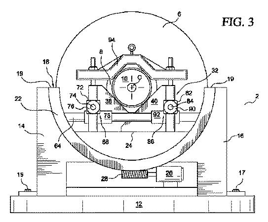
[0013] Pinion cradle 2 comprises a base 12, a first support stand 14 and a second support stand 16.
【0010】
  ピニオン架台2は、土台12、第1の支持台14および第2の支持台16を含む。

First support stand 14 is attached to base 12 via suitable removable attachment means such as a plurality of bolts 15 or by brackets.
第1の支持台14は、複数のボルト15のような適当な取り外し可能な取付手段を用いて、またはブラケットによって、土台12に取り付けられている。

Second support stand 16 is attached to base 12 via suitable removable attachment means such as bolts 17 or by brackets. Alternatively, support stands 14, 16 may be attached to base 12 via welding or may be formed integral with the base 12 such as by casting as a single unit.
第2の支持台16は、ボルト17のような適当な取り外し可能な取付手段を用いて、またはブラケットによって、土台12に取り付けられている。あるいはまた、支持台14、16は、溶接を用いて土台12に取り付けられていてもよく、または、例えば鋳造によって単一ユニットとして、土台12と一体的に形成されていてもよい。

Base 12, first support stand 14 and second support stand 16 may be made of cast iron, steel or mineral cast aggregate for example.
土台12、第1の支持台14および第2の支持台16は、鋳鉄、鋼、または鉱物の鋳造物の集合体で作られていてもよい。

Pinion cradle 2 can be placed and/or removed by crane or fork truck and may be clamped down with brackets or bolts to the factory floor or to the frame, table or rotary table of a machining center or a gear manufacturing machine.
例えば、ピニオン架台2は、クレーンまたはフォークトラックによって設置されおよび/または取り除かれることができ、および工場の床に対して、あるいは複合工作機械またはギア製造機械の枠、テーブルまたは回転テーブルに対して、ブラケットまたはボルトを用いてしっかりと固定されていてもよい。

コメント
  • Twitterでシェアする
  • Facebookでシェアする
  • はてなブックマークに追加する
  • LINEでシェアする

ジャッキ

2021-02-27 11:59:17 | 英語特許散策

WO2018041663
Offshore wind energy is becoming more and more important. In particular the last couple of years there has been an enormous increase in the number of wind farms (a grid of windmills placed on the continental shelf in the seas). Not only is the number of offshore windmills increasing, but also their size, i.e. the windmills are getting bigger.
【0002】
  洋上風力エネルギが一層重要になってきている。特にここ数年は、ウインドファーム(海中の大陸棚上に配置された風車網)の個数に大変な増加が見られる。洋上風車の個数が増えるだけでなくサイズも増しており、即ち風車が大きくなりつつある。

The latter brings new challenges in terms of actually installing these offshore windmills. Dedicated huge ships have been built having very large heavy duty cranes placed on top of them.
後者は、それら洋上風車の実設置との絡みで新たな難題を招いている。専用巨大船が建造され、超大型高荷重クレーンがその上に積載されるようになった。

The general idea is to manufacture the windmills onshore in as large parts as possible and then transport these parts to the desired location, where they are placed using the ever-increasing heavy-duty cranes on an earlier prepared offshore windmill pedestal.
その全般的着想は、極力大きな部品の態で風車を陸上製造した上で、それら部品を所望の場所まで輸送し、そこで、以前にも増し高荷重なクレーンを用い、予め準備してある洋上風車ペデスタル(*架台、台座)上にそれら部品を載せる、というものである。

There exists a huge variety of different technologies of preparing and building such windmill pedestals offshore, but that is beyond the scope of this invention.
そうした風車ペデスタルを準備し沖合に建設するテクノロジには非常に多くの種類があるが、それは本発明の技術的範囲外である。

As the size of the offshore windmills increases further, also the size of these dedicated windmill installation ships is increasing.
洋上風車のサイズが更に増すにつれ、それら専用の風車設置船のサイズも増していく。

In order to facilitate the use of a huge crane these ships are provided with a jack-up system such that they lift themselves out of the sea, which makes the ships orientation independent of the waves.
大型クレーンの使用を可能にするため、それらの船には、自船を持ち上げ海から出すことで自船姿勢が波で左右されないようにするジャッキアップシステムが付設される。

It is particularly the operational costs of these ships, which is of concern.
それが特にそれらの船の稼働コスト上の懸案となっている。

US9066452
The computer rack 12 comprises means 22a, 22b of floor support. This support means 22a, 22b is for example four legs with jacks arranged on two tiles 24 and 26 of a computer room in which the installation 10 is found.
【0038】
  コンピュータベイ12は、床での支え手段22a、22bを備える。これらの支え手段22a、22bは、例えば、設備10がその内部に配置されたコンピュータ室の二つのプレート24及び26上に配置された四つのジャッキ付き脚部である。

Two front legs with jacks 22a of the computer rack 12 are arranged on the first tile 24 and two rear legs with jacks 22b of the computer rack 12 are arranged on the second tile 26.
コンピュータベイ12の前方の二つのジャッキ付き脚部22aは第一のプレート24上に配置されており、コンピュータベイ12の後方の二つのジャッキ付き脚部22bは第二のプレート26上に配置されている。

コメント
  • Twitterでシェアする
  • Facebookでシェアする
  • はてなブックマークに追加する
  • LINEでシェアする

垂直外部共振器型面発光レーザ

2021-02-26 17:52:48 | 単語

垂直外部共振器型面発光レーザ:vertical external-cavity surface-emitting laser (VECSEL)

コメント
  • Twitterでシェアする
  • Facebookでシェアする
  • はてなブックマークに追加する
  • LINEでシェアする

突出して形成

2021-02-26 15:22:10 | 英語特許散策

WO2018147940
[0044] The structure of Figure 1 A, including any of the example patterns of Figures 1B-1K, can be formed, for example, by semiconductor fabrication techniques, such as by forming metal lines on a substrate by deposition, patterning and etching and depositing oxide thereover, or by damascene processing.
【0022】
  図1B~図1Kの例示的パターンのいずれかを含む、図1Aの構造体は、例えば、堆積、パターニング、及びエッチングによって基板上に金属線を形成し、その上に酸化物を堆積させることによって、又はダマシン処理によってなど半導体製造技術によって形成され得る。

Desirably, the metal lines to be bonded are formed flush with surrounding non-conductive material, or slightly (e.g., 0.5 nm to 20 nm) recessed or protruding from the non-conductive material.
望ましくは、接合される金属線は、包囲する非導電性材料と同一平面に、又は非導電性材料からわずかに(例えば、0.5nm~20nm)凹んで、若しくは突出して形成される。

Annular or mostly annular patterns of metal lines can be formed on both semiconductor elements 3, 2 using semiconductor processing, for directly bonding to one another and creating an effective metal seal against gas diffusion.
金属線の環状又はほぼ環状のパターンは、半導体加工を用いて両半導体素子3、2上に形成され、互いに直接接合して、気体拡散に対して有効な金属封止を作り出し得る。

WO2015126865
In this respect US 2010/075276 (Shofu) describes a storage container for a dental adhesive, comprising an elongated container portion that can store a liquid therein,
【0009】
  この点において、米国特許第2010/075276号(Shofu)は、内部に液体を保存することができる細長い容器部分を含む、歯科用接着剤のための保存容器を記載しており、

wherein one end surface of said container portion has a discharge port communicating with an outside,
該容器部分の一方の末端面は、外部と連通する放出ポートを有し、

the other end surface of said container portion is closed by a bottom wall, and a tail portion is formed protruding from said bottom wall to the side opposite from the discharge port.
該容器部分の他方の末端面は、底部壁により閉鎖され、後部部分は底部壁から、放出ポートの反対側に突出して形成されている。

WO2015079332
It should further be appreciated that the cover member 46 may be variously configured within the scope and spirit of the invention.
【0034】
  また、カバー部材46は、本発明の範囲および精神の範囲内で、様々な構成をとることができることを理解されたい。

In the illustrated embodiment, the cover member 46 has a distal end with an overhanging first lip 60 that extends over the perimeter wall 38 in the closed position of the cover member 46, as particularly illustrated in Fig. 1.
図示した実施形態では、カバー部材46は、その遠位端に、カバー部材46から突出して形成された第1のリップ60を有している。図1に特に示すように、第1のリップ60は、カバー部材46の閉位置において、外周壁38を越えて延在する(すなわち、外周壁38の外側に位置する)。

This lip 60 has a slot 62 defined therein that aligns with the slot 44 in the perimeter wall 38 in the closed position of the cover member 48.
第1のリップ60には、カバー部材46の閉位置において外周壁38のスロット44と整合するスロット62が形成されている。

With this configuration, the cover member 46 can be closed with a catheter 28 inserted into the passage 24 in the connector body 14, with the first lip 60 and slot 62 engaging around the catheter.
この構成により、カバー部材46の閉位置において、コネクタ本体部14の流路遠位端24に挿入されたカテーテル26の外周面に、第1のリップ60およびスロット62が係合することができる。

EP1350537
[0067] A twelfth embodiment of the subject invention is illustrated in FIGS. 24 and 25 and is similar to the eleventh embodiment. More particularly, the twelfth embodiment includes a needle 34 and a needle hub 36.
【0040】
  本発明の第12実施例は、図24、25に示すように、第11実施例と類似している。すなわち、第12実施例の針アセンブリは針34と針ハブ36とを有する。

Needle hub 36 includes a distal end 48 and needle cannula 34 extends therefrom. Wings 54 and 55 project transversely from hub 36.
針ハブ36は、先端部48と、そこから延びる針状カニューレ34とを備えている。翼部54,55は、ハブ36に対し横方向に突出して形成されている。

A needle shield 170 is hingedly connected to distal end 48 of needle hub 36.
針の被覆部材170は、針ハブ36の先端部48にヒンジ接続されている。

コメント
  • Twitterでシェアする
  • Facebookでシェアする
  • はてなブックマークに追加する
  • LINEでシェアする

麻原彰晃の発明

2021-02-26 14:29:56 | 雑感

特開平05-322145

流動床焼却炉


一体何を焼却するつもりだったのか?

コメント
  • Twitterでシェアする
  • Facebookでシェアする
  • はてなブックマークに追加する
  • LINEでシェアする

野口五郎さんの発明

2021-02-26 14:22:59 | 雑感

特許4859882
コンテンツ配信システムおよびコンテンツ配信方法

コメント
  • Twitterでシェアする
  • Facebookでシェアする
  • はてなブックマークに追加する
  • LINEでシェアする

ブライアン・メイの発明

2021-02-26 14:10:54 | 雑感

GB2472255
(Ab)
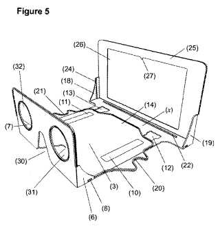
A collapsible fully focusing stereoscope with prismatic effect is suitable for viewing stereo book illustrations or classic stereo slides, may be moulded in only two parts, in flexible plastic and may have integrally moulded hinges (1, fig 1 and 15, fig 3). The two parts slide on runners 10, 11 which fit into(*嵌合、収まる、はまる)slots 12, 13 to make a focusing adjustment by allowing the lenses to move in relation to the back plate 25 which can accommodate stereo slides. The adjustment is controlled by thumb locators 20, 21. The whole instrument folds up(*畳める、折り畳む)to allow storage in an envelope only 6mm thick. The lens apertures 31, 32 are set so that the centers of the lenses are just a little further apart than the human eyes, in order to produce a prismatic effect.

First page clipping of GB2472255 (A)

Brian May Launches OWL VR Smart Phone Kit

コメント
  • Twitterでシェアする
  • Facebookでシェアする
  • はてなブックマークに追加する
  • LINEでシェアする

エディーの発明

2021-02-26 13:32:30 | 雑感

昨年亡くなったエドワード・バン・ヘイレンの発明。

US4656917
What is claimed is:

1. A stringed musical instrument comprising an instrument body having front and rear surfaces, sound producing means extending over(*延在)a portion of said front surface, and a device mounted onto said rear surface for positioning said instrument body at an angular orientation to a player's body, said device including attachment means movable between an inoperative position overlying(*重なる、上に位置、上に配設、重畳、上に延在)said rear surface and an operative position at an angle to said rear surface, a pair of spaced-apart(*離間)mounting blocks attached to said rear surface and support means coupled to said mounting blocks for rotationally supporting therebetween(*前置詞の前置)said attachment means, said attachment means engaging(*係合)said player's body when in said operative position for maintaining said instrument body in said angular orientation and disengaging from said player's body when in said inoperative position for maintaining said instrument body in other than said angular orientation(*以外の、前記角度配置以外の配置に).

コメント
  • Twitterでシェアする
  • Facebookでシェアする
  • はてなブックマークに追加する
  • LINEでシェアする

相手装置

2021-02-25 21:07:17 | 英語特許散策

WO2018236650
[0039] FIG. 3 is a diagram showing how item 12 may be a keyboard that is attached to mating equipment such as device 18. Device 18 may be, for example, a tablet computer having a touch screen display such as display 32.
【0039】
  図3は、アイテム12がどのようにデバイス18などの相手装置に取り付けられているキーボードであり得るかを示す図である。デバイス18は、例えば、ディスプレイ32などのタッチスクリーンディスプレイを有するタブレットコンピュータであってよい。

Item 12 may be a stand-alone keyboard, a keyboard that forms part of a case (e.g., a protective cover), and/or may be part of other accessory equipment configured to operate with device 18.
アイテム12は、独立型のキーボード、ケース(例えば、保護カバー)の一部を形成するキーボード、であってよく、及び/又はデバイス18で動作するように構成される他のアクセサリ装置の一部であってよい。

Device 18 may be coupled to item 12 wirelessly and/or may have a connector such as connector 30 that mates with a corresponding connector in item 12 such as connector 28.
デバイス18はアイテム12に無線接続されてよく、及び/又はコネクタ28などのアイテム12における対応するコネクタと噛み合うコネクタ30などのコネクタを有してもよい。

If desired, magnets or other fastening mechanisms may be provided in item 12 and device 18 to hold item 12 and device 18 together. Item 12 may have a rectangular shape and may, if desired, have a folding flap (e.g., when item 12 forms part of a cover for device 18).
所望であれば、アイテム12及びデバイス18を共に保持するために、磁石又は他の締結機構をアイテム12及びデバイス18に設けてもよい。アイテム12は、長方形の形状を有してもよく、所望であれば、折り畳みフラップ(例えば、アイテム12がデバイス18用のカバーの一部を形成する場合)を有してもよい。

US7992014
The method of FIG. 2 also includes querying (212), by the power supply communications device (208) of the first power supply (202), for a maximum current threshold (216) for the circuit breaker (204).
【0022】
  図2の方法は、第一電源(202)の電源交信装置(208)がブレーカ(204)に対する最大電流閾値(216)を問い合わせるステップ(212)をさらに含む。

In the method of FIG. 2 querying (212) for a maximum current threshold (216) may be carried out by querying the circuit breaker communications device for the maximum current threshold over radio frequencies (‘RF’).
図2の方法において、最大電流閾値(216)を問い合わせるステップ(212)は、無線周波数(「RF」)を介して、ブレーカ交信装置に最大電流閾値を問い合わせるステップによって実施することができる。

As mentioned above, Insteon devices can communicate with one another over the power line or over RF or both.
前述したように、インステオン装置は、電力線、又はRFあるいはその両方を介して相互に通信することができる。

Once the power supply communications device identifies the particular circuit breaker communications device through the power line, the power supply communications device may send a query to the particular circuit breaker communications device by using the device's unique identification.
電源交信装置が電力線を介して特定のブレーカ交信装置を識別したならば、該電源交信装置は、相手装置に固有の識別番号を使って特定のブレーカ交信装置に問い合わせを送信することができる。

In this way, even if multiple circuit breaker communications devices are near enough to communicate via RF they query is directed to the correct circuit breaker communications device.
このようにして、RFを介して通信するには近すぎる複数のブレーカ交信装置がある場合でも、問い合わせは正しいブレーカ交信装置に向け送信される。

Once the power supply communications device receives the circuit breaker identification and the maximum current threshold for the circuit breaker, the method of FIG. 2 proceeds by sending (214), by the power supply communications device (208) through the out-of-band communications link, the circuit breaker identification (218) and the maximum current threshold (216) for the circuit breaker (204) to the management module (160).
電源交信装置が該ブレーカのブレーカ識別番号と最大電流閾値とを受信したならば、図2の方法は、該電源交信装置(208)が帯域外通信リンクを介して、該ブレーカ識別番号(218)とブレーカ(204)に対する最大電流閾値(216)とを管理モジュール(160)に送信するステップ(214)に進む。

WO2006113899
[0014] In one example, capacity manager 116 may monitor available space in a device's (e.g., switch element 112 or endpoints 114) VC queue for a point-to-point communication link with a link partner device.
【0014】
  一例では、容量マネージャ116は、リンク相手装置とのポイント・ツー・ポイント通信について装置(例えばスイッチ要素112又はエンドポイント114)のVCキューの利用可能空間を監視してもよい。

WO2004019535
(Ab)
The invention relates to a system and method for use in wireless packet data mode communications for enabling communication between a source device (102a) and one or more target devices (102b) with a reduced set-up time.
本発明は、発信装置(102a)と1つ以上の相手装置(102b)との間の、通信時間の短縮を可能にする無線パケットデータモード通信に使用する、システムと方法に関する。

The invention captures in a control structure (600), one or more communication parameters (602-608) during the set up of the source device (102) and a base station (106).
本発明は、制御構造(600)中で、発信装置(102)と基地局(106)との間の通信設定の際に1つ以上のパラメータ(602~608)を捕捉する。

Then the control structure (600) is transmitted to the one or more target devices (102b) during the period of the source device's (102a) configuration and is utilized to configure the one or more target devices (102b) to communicate with the source device (102a) via the base station (106), thus reducing the total time required to set-up the communications.
 次に、発信装置(102a)を構築している間に、この制御構造(600)が1つ以上の相手装置(102b)に送信されて、基地局(106)を介して発信装置(102a)と1つ以上の相手装置(102b)との間の通信を構築するために使用される。それによって、通信を設定するために必要な全時間が短縮される。

EP1623586
Figure 10 illustrates an exemplary communications system 1000 in accordance with one particular exemplary embodiment of the present invention.
【0040】
  図10は、本発明の特定の一例示的実施形態による例示的通信システム1000を示す。

The system 1000 includes a first node, e. g. , mobile node 1001, a second node, e. g. , access node 1003 which may be used as a MIP Foreign Agent, a third node, e. g. , a regional mobility agent node 1005 which may be a MIP home agent,
システム1000は、モバイルノード1001などの第1のノードと、MIPフォーリンエージェントとして使用しうるアクセスノード1003などの第2のノードと、MIPホームエージェントとして使用しうる域内モビリティエージェントノード1005などの第3のノードと、

a fourth node, e. g. , a communication peer node 1007 sometimes called a correspondence node, fifth node, e. g. , a network node 1009, and a sixth node, e. g. , an access node 1011. Mobile node (MN) 1001 is coupled to access node 1003 via wireless link 1013.
通信相手ノードとも呼ばれる通信ピアノード1007などの第4のノードと、ネットワークノード1009などの第5のノードと、アクセスノード1011などの第6のノードとを含む。

WO2010088482
[0008] Furthermore, the subject specification discloses a mechanism for tracking and reporting peer-to-peer usage of wireless resources and wireless data consumption.
【0008】
  さらに、主題的な明細書は、ピア・ツー・ピアワイヤレスリソースの使用とワイヤレスデータ消費とを追跡し、報告するためのメカニズムを開示している。

Usage reports submitted to the network server based on ad-hoc data exchange can identify an ad-hoc partner, or amount of data associated with such data exchange.
アドホックデータ交換に基づいて、ネットワークサーバに提出された使用報告は、アドホックの相手を、または、このようなデータ交換に関係付けられているデータの量を識別することができる。

Accordingly, the network server can cross-verify reported data submitted by multiple ad-hoc communication partners as an additional cross-check on veracity of reported information.
したがって、ネットワークサーバは、報告された情報の信憑性に関する付加的な相互チェックとして、複数のアドホック通信の相手により提出された、報告されたデータを相互検証することができる。

In at least one aspect, at the end of a peer-to-peer communication session, two or more terminals can exchange accounting records of a completed session for crosschecking, and respectively can obtain a summary of the session digitally signed by a private key particular to the partner terminal.
少なくとも1つの側面では、ピア・ツー・ピア通信セッションの終わりに、2つ以上の端末が、相互チェックのために、完了したセッションのアカウンティング記録を交換することができ、相手端末に特有のプライベート鍵によりデジタル署名されているセッションのサマリーを、それぞれ取得することができる。

Crosschecking and cross signing enables additional system optimizations, such as employing a single peer-to-peer partner to submit accounting records for a session, which are signed by both partners.
単一のピア・ツー・ピアの相手を用いて、双方の相手により署名されている、セッションに対するアカウンティング記録を提出するような、付加的なシステム最適化が、相互チェックおよび相互署名により可能になる。

Which terminal performs the reporting can be negotiated/configured or determined statistically, and by mutual agreement of modules of such terminals.
どの端末が報告を実行するかは、交渉することができ/統計的に、または、このような端末のモジュールの相互合意により、構成または決定することができる。

コメント
  • Twitterでシェアする
  • Facebookでシェアする
  • はてなブックマークに追加する
  • LINEでシェアする

無線フレーム

2021-02-25 20:40:59 | 英語特許散策

EP3342228
[0092] Flexible framing may be used in wireless communications systems such as a 5gFLEX system for downlink and uplink transmissions.
【0081】
  柔軟なフレーミングは、ダウンリンクおよびアップリンク送信の5gFLEXシステムのような無線通信システムにおいて使用されてもよい。

Downlink and uplink transmissions may be organized into radio frames characterized by a number of fixed aspects (e.g., location of downlink control information) and a number of varying aspects (e.g., transmission timing, supported types of transmissions).
ダウンリンクおよびアップリンク送信は、複数の固定の態様(たとえば、ダウンリンク制御情報の位置)および複数の可変の態様(たとえば、送信タイミング、サポートされる送信のタイプ)によって特徴付けられる無線フレームに編成されてもよい。

One or more of such aspects may differ in terms of the radio frame arrangement between different types of transmissions, between transmissions of the same WTRU (e.g., spectrum operation mode (SOM)-specific framing structure), between transmissions of different WTRUs (e.g., WTRU-specific framing structure), and between transmissions in the downlink direction and in the uplink direction.
1つまたは複数のそのような態様は、異なる送信のタイプの間、同じWTRUの送信の間(たとえば、スペクトル操作モード(SOM)固有のフレーミング構造)、異なるWTRUの送信の間(たとえば、WTRU固有のフレーミング構造)、およびダウンリンク方向およびアップリンク方向の送信の間で、無線フレーム配置に関して異なることがある。

The timing relationships supported by the flexible frame structure may be indicated to the WTRU dynamically or semi-statically as shown in the examples described herein.
柔軟なフレーム構造によりサポートされるタイミング関係は、本明細書において説明される例に示されているようにWTRUに動的または半静的に表示されてもよい。

EP3729753
[0036] The base station may also be referred to as a gNB, Node B, evolved Node B (eNB), an access point, a base transceiver station, a radio base station, a radio transceiver, a transceiver function, a basic service set (BSS), an extended service set (ESS), a transmit reception point (TRP), or some other suitable terminology.
【0027】
    [0036]
  基地局はまた、gNB、ノードB、進化型ノードB(eNB)、アクセスポイント、基地トランシーバ局、無線基地局、無線トランシーバ、トランシーバ機能、基本サービスセット(BSS)、拡張サービスセット(ESS)、送受信ポイント(TRP)、または、他の何らかの適した専門用語として呼ばれることがある。

The base station 102 provides an access point to the EPC 160 or 5GC 190 for a UE 104.
基地局102は、UE104のためにEPC160または5GC190へのアクセスポイントを提供する。

Examples of UEs 104 include a cellular phone, a smart phone, a session initiation protocol (SIP) phone, a laptop, a personal digital assistant (PDA), a satellite radio, a global positioning system,
UE104の例は、セルラー電話機、スマートフォン、セッション開始プロトコル(SIP)電話機、ラップトップ、パーソナルデジタルアシスタント(PDA)、衛星無線、グローバルポジショニングシステム、

a multimedia device, a video device, a digital audio player (e.g., MP3 player), a camera, a game console, a tablet, a smart device, a wearable device, a vehicle, an electric meter, a gas pump, a large or small kitchen appliance, a healthcare device, an implant, a sensor/actuator, a display, or any other similar functioning device.
マルチメディアデバイス、ビデオデバイス、デジタルオーディオプレーヤー(例えば、MP3プレーヤー)、カメラ、ゲームコンソール、タブレット、スマートデバイス、ウェアラブルデバイス、車両、電気メーター、ガスポンプ、大きなまたは小さな台所用品、ヘルスケアデバイス、インプラント、センサ/アクチュエータ、ディスプレイ、あるいは、他の何らか同様の機能的なデバイスを含んでいる。

Some of the UEs 104 may be referred to as IoT devices (e.g., parking meter, gas pump, toaster, vehicles, heart monitor, etc.).
UE104のうちのいくつかは、IoTデバイス(例えば、パーキングメーター、ガスポンプ、トースター、車両、心臓モニタなど)として呼ばれることがある。

The UE 104 may also be referred to as a station, a mobile station, a subscriber station, a mobile unit, a subscriber unit, a wireless unit, a remote unit, a mobile device, a wireless device, a wireless communications device, a remote device,
UE104はまた、局、移動局、加入者局、移動体ユニット、加入者ユニット、ワイヤレスユニット、遠隔ユニット、移動体デバイス、ワイヤレスデバイス、ワイヤレス通信デバイス、遠隔デバイス、

a mobile subscriber station, an access terminal, a mobile terminal, a wireless terminal, a remote terminal, a handset, a user agent, a mobile client, a client, or some other suitable terminology.
移動体加入者局、アクセス端末、移動体端末、ワイヤレス端末、遠隔端末、ハンドセット、ユーザエージェント、移動体クライアント、クライアント、または、他の何らかの適切な専門用語として呼ばれることがある。

EP3031262
[0001] Cellular communication networks may be configured to enable direct Device-to-Device (D2D) communications, for example, between wireless transmit/receive units (WTRUs) located within radio range of each other.
【0002】
  セルラー通信ネットワークは、例えば、互いの無線範囲内に位置する無線送受信ユニット(WTRU)間で、直接デバイスツーデバイス(D2D)通信を可能にするように構成されることができる。

Enabling D2D communications may enhance the spectrum efficiency of a cellular communications network, for example by allowing devices (e.g., WTRUs) to communicate with each other directly rather than sending communications to each other via a corresponding core network.
D2D通信を可能にすることは、例えば、デバイス(例えば、WTRU)が、対応するコアネットワークを介して互いに対して通信を送るのではなく、互いに直接通信するよう許可することによって、セルラー通信ネットワークのスペクトル効率を高めることができる。

D2D communications may allow devices (e.g., WTRUs) to communicate with each other autonomously even in absence of coverage by a cellular communications network or networks are unavailable due to outage or failure.
D2D通信は、セルラー通信ネットワークによるカバレッジの不在の場合、または停電もしくは障害に起因してネットワークが利用不可能の場合でさえ、デバイス(例えば、WTRU)が互いに自律的に通信するのを許可することができる。


[0008] The WTRU may determine and/or select the SA resource based on the characteristics of the data to be transmitted.
【0008】
  WTRUは、送信されることになるデータの特徴に基づいて、SAリソースを判定し、および/または選択することができる。

For example, the WTRU may determine and/or select the SA resource based on one or more of the quality of service (QoS) (and/or QoS class identifier (QCI)), traffic type (e.g., delay-sensitive vs non-delay-sensitive), application or other characteristic associated to the data, logical channel priorities, etc.
例えば、WTRUは、サービス品質(QoS)(および/またはQoSクラス識別子(QCI))、トラフィックタイプ(例えば、遅延センシティブ対非遅延センシティブ)、アプリケーションまたはデータに関連付けられた他の特徴、論理チャネル優先度などのうちの、1または複数に基づいて、SAリソースを判定し、および/または選択することができる。

The association between the SA or set of SAs within the set of allowed SA and the data characteristics may be configured (e.g., pre-configured) in the application, the Universal Subscriber Identity Module (USIM), or via Radio Resource Control (RRC) signaling.許可されたSAのセット内のSAまたはSAのセットと、データ特徴との間の関連付けは、アプリケーション、ユニバーサル加入者アイデンティティモジュール(USIM)において、または無線リソース制御(RRC)シグナリングを介して、構成(例えば、事前構成)されることができる。


[0023] FIG. 1A is a diagram of an example communications system 100 in which one or more disclosed embodiments may be implemented.
【0023】
  図1Aは、1または複数の開示される実施形態が実施されうる例示的な通信システム100の図である。

The communications system 100 may be a multiple access system that provides content, such as voice, data, video, messaging, broadcast, etc., to multiple wireless users.
通信システム100は、音声、データ、ビデオ、メッセージング、放送などのコンテンツを複数の無線ユーザに提供する多元接続システムを含むことができる。

The communications system 100 may enable multiple wireless users to access such content through the sharing of system resources, including wireless bandwidth.
通信システム100は、複数の無線ユーザが、無線帯域幅を含むシステムリソースの共用を通して、そのようなコンテンツにアクセスすることを可能にする。

For example, the communications systems 100 may employ one or more channel access methods, such as code division multiple access (CDMA), time division multiple access (TDMA), frequency division multiple access (FDMA), orthogonal FDMA (OFDMA), single-carrier FDMA (SC-FDMA), and the like.
例えば、通信システム100は、CDMA、TDMA、FDMA、直交FDMA(OFDMA)およびシングルキャリアFDMA(SC-FDMA)など、1または複数のチャネルアクセス方法を利用することができる。

[0024] As shown in FIG. 1A , the communications system 100 may include at least one wireless transmit/receive unit (WTRU), such as a plurality of WTRUs, for instance WTRUs 102a, 102b, 102c, and 102d, a radio access network (RAN) 104, a core network 106, a public switched telephone network (PSTN) 108, the Internet 110, and other networks 112,
【0024】
  図1Aに示されるように、通信システム100は、複数の無線送受信ユニット(WTRU)、例えば、WTRU102a、102b、102cおよび102dのような少なくとも一つのWTRU、無線アクセスネットワーク(RAN)104、コアネットワーク106、公衆交換電話網(PSTN)108、インターネット110および他のネットワーク112を含むことができるが、

though it should be appreciated that the disclosed embodiments contemplate any number of WTRUs, base stations, networks, and/or network elements.
開示される実施形態は、任意の数のWTRU、基地局、ネットワーク、および/またはネットワーク要素を企図していることが理解されよう。

Each of the WTRUs 102a, 102b, 102c, 102d may be any type of device configured to operate and/or communicate in a wireless environment.
WTRU102a、102b、102c、102dの各々は、無線環境において動作および/または通信するように構成された任意のタイプのデバイスとすることができる。

By way of example, the WTRUs 102a, 102b, 102c, 102d may be configured to transmit and/or receive wireless signals and may include user equipment (UE), a mobile station, a fixed or mobile subscriber unit, a pager, a cellular telephone, a personal digital assistant (PDA), a smartphone, a laptop, a netbook, a personal computer, a wireless sensor, consumer electronics, and the like.
例えば、WTRU102a、102b、102c、102dは、無線信号を送信および/または受信するように構成されることができ、ユーザ機器(UE)、移動局、固定若しくは移動加入者ユニット、ページャ、セルラー電話、携帯情報端末(PDA)、スマートフォン、ラップトップ、ネットブック、パーソナルコンピュータ、無線センサおよび家電製品などを含むことができる。


[0289] The WTRU may be configured to determine the bandwidth of a system.
【0300】
  WTRUは、システムの帯域幅を判定するように構成されうる。

The WTRU may be determined to start measuring identified subframes to determine which frequency and time resource combinations are least interfered. Frequency may comprise RBs.
WTRUは、識別されたサブフレームの測定を開始して、どの周波数リソースおよび時間リソースの組合せが、最も少なく干渉されるかを判定するように構成されうる。周波数はRBを備えることができる。

Time may comprise subframes.
時間はサブフレームを備えることができる。

For example, the WTRU may be configured to determine that, in the entire system bandwidth of 10 MHz in subframes 7, 8, and 9, one or more even radio frame may be allowed for D2D transmission in the vicinity and start measuring those identified subframes to determine which particular combinations of frequency and/or time resources are least interfered.
例えば、WTRUは、サブフレーム7、8および9における10MHzの全体のシステム帯域幅において、1または複数の偶数無線フレームが近傍においてD2D送信のために許可され得ることを判定し、それらの識別されたサブフレームの測定を開始して、周波数リソースおよび/または時間リソースのどの特定の組合せが最も少なく干渉されるかを判定するように構成されうる。

コメント
  • Twitterでシェアする
  • Facebookでシェアする
  • はてなブックマークに追加する
  • LINEでシェアする

明細書の先行技術文献番号

2021-02-25 17:43:49 | メモ

日本語明細書の先行技術文献として「国際公開第2011/000000号」とあるからEspacenetのPublication numberでWO2011/000000と入れたが、対応文献が出てこない。

Application numberにPCT/JP2011/000000を入れたら出てきた。

コメント
  • Twitterでシェアする
  • Facebookでシェアする
  • はてなブックマークに追加する
  • LINEでシェアする

偏波両用

2021-02-25 14:39:52 | 英語特許散策

US2020379086(JP)
[0043] The object shape detection apparatus 6 is a frequency modulated continuous wave (FMCW) radar consisting of a transmit unit 7 and a receive unit 8.
【0035】
  物体形状検出装置6は、送信部7と受信部8とから構成されるFMCW(Frequency Modulated Continuos Wave)レーダーである。

The transmit unit 7 includes a voltage controller 71, a voltage-controlled oscillator (VCO) 72, a splitter 73, a polarized wave switch 74, and a horizontally and vertically polarized waves dual transmit antenna 75.
送信部7は、電圧制御部71、VCO(Voltage-controlled oscillator:電圧制御発振器)72、分配器73、偏波切替部74、並びに、水平および垂直偏波両用送信アンテナ75を備える。

The VCO 72 produces a modulated high frequency signal in the GHz band that has been subjected to frequency modulation because the voltage controller 71 controls the voltage applied to the VCO 72. The high frequency signal is outputted to the polarized wave switch 74 via the splitter 73.
VCO72は、その印加電圧が電圧制御部71によって制御されることで、周波数変調されたGHz帯の高周波信号を発振する。この高周波信号は分配器73を介して偏波切替部74に出力される。

The polarized wave switch 74 outputs a horizontally polarized wave component and a vertically polarized wave component of the inputted high frequency signal to the horizontally and vertically polarized waves dual transmit antenna 75 while switching between a horizontally polarized wave component and a vertically polarized wave component in a time division manner.
偏波切替部74は、入力した高周波信号の水平偏波成分および垂直偏波成分を時分割に切り替えて、水平および垂直偏波両用送信アンテナ75へ出力する。

As a result, an electromagnetic wave of the horizontally polarized wave component subjected to frequency modulation and an electromagnetic wave of the vertically polarized wave component subjected to frequency modulation are alternately emitted from the horizontally and vertically polarized waves dual transmit antenna 75 at fixed time intervals.
したがって、水平および垂直偏波両用送信アンテナ75からは、周波数変調された水平偏波成分の電磁波と垂直偏波成分の電磁波とが一定時間毎に交互に放射される。

The transmit unit 7 constitutes a transmitter that emits, as a continuous wave, a horizontally polarized wave component and a vertically polarized wave component of an electromagnetic wave subjected to frequency modulation.
送信部7は、周波数変調される電磁波の水平偏波成分および垂直偏波成分を連続波として放射する送信器を構成する。

EP1986269(JP)
[0006] Furthermore, Patent Document 3 discloses a thin planar antenna capable of dealing with a horizontally polarized wave and a vertically polarized wave, or a left-handed circularly polarized wave and a right-handed circularly polarized wave. In the planar antenna disclosed in Patent Document 3, a loop-shaped antenna element is arranged in parallel with a ground plane, and first and second feeding conductors having feeding points shifted by 90° are arranged between a loop element and the ground plane.
【0006】
  更に、水平偏波と垂直偏波、または左旋円偏波と右旋円偏波に対応できる薄型平面アンテナも知られている(例えば、特許文献3参照)。特許文献3に開示された平面アンテナでは、ループ形のアンテナ素子をグランドプレーンと平行に配置し、給電点が90°変位している第1及び第2の給電導体をループ素子とグランドプレーンとの間に配置している。

The first and the second feeding conductors are connected to central conductors of first and second coaxial lines, respectively, and external conductors of the first and the second coaxial lines are connected to the ground plane to feed the antenna element through electromagnetic coupling. In case of feeding from the first feeding conductor, the horizontally polarized wave is radiated. In case of feeding from the second feeding conductor, the vertically polarized wave is radiated.
第1及び第2の給電導体に、それぞれ、第1及び第2の同軸線路の中心導体を接続し、第1及び第2の同軸線路の外部導体をグランドプレーンに接続して、電磁結合によりアンテナ素子に給電する。第1の給電導体から給電した場合は水平偏波が放射され、第2の給電導体から給電すると垂直偏波が放射される。

By switching the first and the second feeding conductors, it is possible to transmit/receive the horizontally polarized wave and the vertically polarized wave. Further, if the loop element is provided with a perturbation element, the antenna becomes an antenna for left-handed/right-handed circularly polarized waves.
第1及び第2の給電導体をスイッチすることにより、水平偏波と垂直偏波を送受信できる。また、ループ素子に摂動素子を設ければ、左旋/右旋円偏波両用アンテナになる。

コメント
  • Twitterでシェアする
  • Facebookでシェアする
  • はてなブックマークに追加する
  • LINEでシェアする

当ブログの例文について

本ブログの「特許英語散策」等題した部分では、英語の例文を管理人の独断と偏見で収集し、適宜訳文・訳語を記載しています。 訳文等は原則として対応日本語公報をそのまま写したものです。私個人のコメント部分は(大抵)”*”を付しています。 訳語は多数の翻訳者の長年の努力の結晶ですが、誤訳、転記ミスもあると思いますのでご注意ください。