『必要?不必要?スーパーツィーター vol.17』の続きです。
ここまで顕著な改善がされると、さらに欲がでてきます。
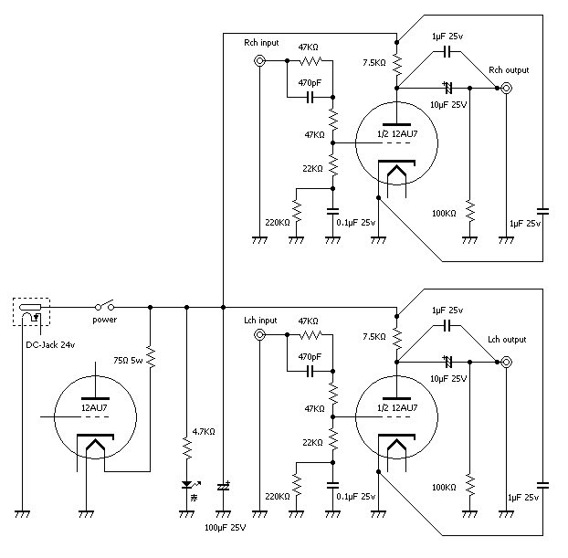
現在実験中の試作機No.2の回路図は以下の通りですが、

これにパスコン(バイパス・コンデンサー)を追加してみましょう。
電解コンデンサーは高域特性が悪いため、
高域特性が良いフイルムコンデンサーをバイパスとして並列接続します。
今回は超高域の信号に対する機器なので効果は大きいとおもいます。
パスコンを入れた試作機No.3の回路図です。
赤丸がパスコンです。
回路図で表現するとあっけないのですが、
実際の接続は次のように行います。
2つの回路図の違いは・・・次回に続きます。
Necessity? Unnecessary ? super tweeter vol.18
It is a continuation of "Necessity? Unnecessary ? super tweeter vol.17"
Furthermore, let's carry out a big improvement.
The circuit diagram of experimental model No.2
A bypass capacitor is added.
Since the treble characteristic of an electrolytic condenser is bad,
the treble characteristic carries out multiple connection of
it by considering a good film capacitor as a bypass.
I think that an effect is large to the signal of the number of extremely high frequency.
The circuit diagram of experimental model No.3
The red mark is a bypass capacitor.
Expression of a circuit diagram is simple.
Actual connection is made as follows.
The difference between two circuit diagrams ...
To be continued.