WO2008156674
28. The trench gate IGBT of claim 27, further comprising: a N+ buffer epitaxial layer disposed between the P type emitter epitaxial layer and the N- base epitaxial layer.
更に、前記P型エミッターエピタキシャル層と、前記N型ベースエピタキシャル層の間に配置されたN+型バッファーエピタキシャル層とを備える請求項27に記載のトレンチゲート型絶縁ゲートバイポーラデバイス。
WO2013173414
10. The semiconductor device (200) of Claim 1, wherein the silicon carbide substrate (202) has a n+-type conductivity type,
【請求項10】
前記シリコンカーバイド基板(202)は、n+型導電型を有し、
wherein the first dopant type is p-type, such that the first conductivity type is p-type, and wherein the second dopant type is n-type, such that the second conductivity type is n-type.
前記第1の導電型がp型になるように、前記第1のドーパント型はp型であり、前記第2の導電型がn型になるように、前記第2のドーパント型はn型である、請求項1に記載の半導体デバイス(200)。
US5374569
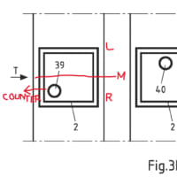
FIG. 22 is a cross-sectional view of a first embodiment of a lateral DMOS transistor structure.
図38は、ラテラルDMOSトランジスタ構造の第1実施例の断面図である。
N- epitaxial layer 40 having an upper surface is disposed over substrate layer 10.
上側主面を有するN-エピタキシャル層40が、基層10の上に配置されている。
A P- well region 230 extends downward into the epitaxial layer 40 from the upper surface of the epitaxial layer.
P-ウェル領域230は、エピタキシャル層の上側主面からエピタキシャル層40内へ下向きに延出している。
A field oxide layer, comprised of field oxide portion 231 and 232, and field oxide portion 232, is disposed on the upper surface of the epitaxial layer 40.
フィールド酸化膜部分231及び232、及びフィールド酸化膜部分233からなるフィールド酸化膜が、エピタキシャル層40の上側主面上に配置されている。
Field oxide portion 231 and 233 defines an active area 234.
フィールド酸化膜部分231及び233が活性領域234を画定している。
A P type field implant region 235 and 236 is disposed underneath field oxide portion 231 and 233 where the field oxide portion 231 and 233 overlies the P- type silicon of the well region 230.
フィールド酸化膜部分231及び233がウェル領域230のP-型シリコンを覆う、P型フィールド注入領域235及び236が、フィールド酸化膜部分231及び233の下に配置されている。
Similarly, an N type field implant region 237 and 238 is disposed underneath the field oxide portion 231 and 233 where the field oxide portion 231 and 233 overlies the N- type silicon of the epitaxial layer.
同様に、フィールド酸化膜部分231及び233がエピタキシャル層のN-型シリコンを覆う、N型フィールド注入領域237及び238が、フィールド酸化膜部分231及び233の下に配置されている。
WO20170223403
[0028] The disclosure includes both extrinsic and intrinsic semiconductors.
本開示は、外因性半導体および真性半導体の両方を含む。
Intrinsic semiconductors are undoped (pure).
真性半導体はドーピングされていない(純粋である)。
Extrinsic semiconductors are doped, meaning an agent has been introduced to change the electron and hole carrier concentration of the semiconductor at thermal equilibrium.
外因性半導体はドーピングされており、これは熱平衡状態における半導体の電子およびホールのキャリア密度を変更するために物質が導入されることを意味する。
Both p-type and n-type semiconductors are disclosed, with p-types having a larger hole concentration than electron concentration, and n-types having a larger electron concentration than hole concentration.
p-型半導体およびn-型半導体の両方が開示されるが、p-型は電子密度よりも大きなホール密度を有し、またn-型はホール密度よりも大きな電子密度を有する。
いくつかの態様では、基板層102は、図1および2に示すようなp+層106を備えてもよい。
いくつかの態様では、エピタキシャル層202は、図3および図4に示すようなp+層106を備えてもよい。
p+層106は、充電時定数を低減させるため、および接触形成を実現するために用いられてもよい。
いくつかの態様では、p+層106はまた、イオン注入およびアニーリングによって形成されてもよい。
p+層106は、実現可能な最小シート抵抗で可能な限り高くドーピングされてもよい。
いくつかの態様では、p+層106はゲート—ソース間領域に存在してもよい。
いくつかの態様では、p+層106はゲート—ソース間領域、および部分的にはゲートの下にも存在してもよい。
いくつかの態様では、p+層106は、以下でさらに詳細に説明されるような限られた領域に存在してもよい。
いくつかの態様では、p+層106は0.3μm未満の厚さでもよい。
いくつかの態様では、p+層106は0.2μm未満の厚さでもよい。
いくつかの態様では、p+層106は0.1μmから0.3μmの間の厚さでもよい。
いくつかの態様では、p+層106は0.05μmから0.25μmの間の厚さでもよい。
いくつかの態様では、p+層106は0.15μmから0.25μmの間の厚さでもよい
EP2415071
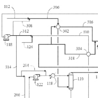
[0035] FIGURE 3 is a cross-sectional view illustrating an exemplary active diode with lightly doped regions according to one embodiment.
図3は、一実施形態による低不純物濃度領域をもつ例示的なアクティブダイオードを示す断面図である。
An active diode 300 includes a substrate 302 having a first doped region 306 (e.g., a P+-type region) and a second doped region 308 (e.g., an N+-type region).
アクティブダイオード300は、第1のドープ領域306(たとえば、P+型領域)と、第2のドープ領域308(たとえば、N+型領域)とを有する基板302を含む。
A first lightly doped region 312 is located between the first doped region 306 and the second doped region 308 and abutted against the first doped region 306.
第1のドープ領域306と第2のドープ領域308の間には、第1の低不純物濃度領域312が位置し、第1のドープ領域306に隣接する。
A second lightly doped region 314 (e.g., a lightly doped drain (LDD)) is located between the first doped region 306 and the second doped region 308 and abutted against the second doped region 308.
第1のドープ領域306と第2のドープ領域308の間には、第2の低不純物濃度領域314(たとえば、低不純物濃度ドレイン(LDD))が位置し、第2のドープ領域308に隣接する。
A salicide layer including a first salicide portion 316 is formed on the first doped region 306 and also including a second salicide portion 318 is formed on the second doped region 308.
第1のドープ領域306上には、第1のサリサイド部分316を含むサリサイド層が形成され、また第2のドープ領域308上には、第2のサリサイド部分318を含むサリサイド層が形成される。
In the active diode 300, current conducts between the first doped region 306 and the second doped region 308 along a path substantially parallel to a surface of the substrate 302.
アクティブダイオード300内では、第1のドープ領域306と第2のドープ領域308の間を、基板302の表面と実質上平行な経路に沿って電流が伝導する。
At the periphery, STI regions 304 are provided.
周辺部では、STI領域304が提供される。
Without an STI region between the first doped region 306 and the second doped region 308, current conduction occurs along a shorter path 330 than in a conventional STI diode.
第1のドープ領域306と第2のドープ領域308の間にSTI領域がないため、電流伝導は、従来のSTIダイオードの場合より短い経路330に沿って行われる。
EP2409334
[0020] Referring now to FIG. 3, to increase the current carrying capability of the reversed biased junction 206, an interconnecting tunnel junction, or ICTJ 302, is epitaxially grown between the top cell 102 and the bottom cell 104 to create a multijunction solar cell 300.
次に、図3を参照するに、逆バイアス接合206の電流伝達能力を高めるために、相互接続トンネル接合(interconnecting tunnel junction)又はICTJ302を上部セル102と下部セル104との間にエピタキシャル成長させて多接合太陽電池300を形成する。
The ICTJ 302 in the multijunction solar cell 300 comprises a highly doped p+-type layer 304 of GaInAs, GaInP, or AlGaAs, and a highly doped n+-type layer 306 of GaInAs, GaInP, or AlGaAs.
多接合太陽電池300内のICTJ302は、GaInAs、GaInP、又はAlGaAsから成る高濃度ドープp+型層304、及びGaInAs、GaInP、又はAlGaAsから成る高濃度ドープn+型層306を含む。
Through a quantum mechanical process, the highly doped ICTJ 302 allows electrons to penetrate across the depletion region 208,
量子力学的プロセスを経て、高濃度ドープICTJ302によって、電子は空乏領域208を横切って突き抜けることができるので、
allowing an amount of tunneled current 308 to flow across the reverse-biased junction 206 that is proportional to the voltage, as illustrated in the tunnel junction voltage-current graph 310.
或る量のトンネル電流308が、トンネル接合の電圧-電流グラフ310に示すように、電圧に比例する逆バイアス接合206を横切って流れることができる。
WO2015094987
[0053] Overall, although certain materials are described specifically above,
全体的に、特定の材料が具体的に上述されたが、
some materials may be readily substituted with others with other such embodiments remaining within the spirit and scope of embodiments of the present disclosure.
いくつかの材料は、他のこのような実施形態が本開示の実施形態の趣旨及び範囲内にとどまる形で、他のものと容易に置換され得る。
For example, in an embodiment, a different material substrate, such as a group ΙΠ-V material substrate, can be used instead of a silicon substrate.
例えば、実施形態において、III-V族材料基板などの異なる材料基板を、シリコン基板の代わりに用いることができる。
Furthermore, it is to be understood that, where N+ and P+ type doping is described specifically, other embodiments contemplated include the opposite conductivity type, e.g., P+ and N+ type doping, respectively.
更に、N+及びP+型のドーピングが具体的に説明されている所では、企図されている他の実施形態は、反対の導電型、例えば、P+及びN+型のドーピングをそれぞれ含むことを理解されるべきである。
Furthermore, it is to be appreciated that a silicidation approach that can be used in place of an aluminum seed layer for contact formation may also be applicable to front contact solar cells.
更に、接点形成のためのアルミニウムシード層の代わりに用いることができるシリサイド化のアプローチは、フロントコンタクト型太陽電池にも適用可能であることを理解されるべきである。
WO2009155106
An n-type silicon wafer with thermal oxide (i.e., silicon <100> wafer highly doped n+ (arsenic) with a resistivity of <0.005 ohm-cm,
熱酸化物を有するn型シリコンウェーハ(すなわち、ノエル・テクノロジー社(Noel Technologies, Inc.)(カリフォルニア州キャンベル)より販売される、0.005Ωcm未満の固有抵抗となるように高濃度にn+型ドープ(ヒ素)し、
and supplied with a 1000 A thermal oxide (SiO2) on the front surface and coated with 100 A TiN and 5000 A aluminum on the back surface from Noel Technologies, Inc. (Campbell, CA)) was (i) washed with acetone and dried with N2,
前面に1000オングストロームの熱酸化物(SiO2)を与え、後面が100オングストロームのTiN及び5000オングストロームのアルミニウムでコーティングされたシリコン<100>ウェーハ)を、(i)アセトンで洗浄してからN2で乾燥し、
(ii) washed with isopropyl alcohol (IPA) and dried with N2,
(ii)イソプロピルアルコール(IPA)で洗浄してからN2で乾燥し、
(iii) washed with deionized water (DI) water and dried with N2,
(iii)脱イオン水(DI)で洗浄してからN2で乾燥し、
and (iv) then treated with UVVO3 for 10 minutes.
(iv)更にUV/O3で10分間処理した。
The wafer sample was then (i) coated with a ZrOAc solution having a viscosity of 15.3 mPa by spin coating (acceleration rate of 415 RPM/s, final speed of 2000 RPM for 30 seconds),
次いでウェーハ試料を、(i)スピンコーティング(加速率415RPM/秒、最終速度2000RPMで30秒)により15.3mPaの粘度を有する酢酸ジルコニウム(ZrOAc)溶液でコーティングし、
(ii) then heated on a hot plate at 100 C for 10 minutes
(ii)次いでホットプレート上で100℃に10分加熱した後、
followed by (iii) exposure to UV (i.e., 254 nm germicidal lamp) in a nitrogen atmosphere for 15 minutes
(iii)窒素雰囲気中で紫外線(254nm殺菌ランプ)に15分曝露し、
and then (iv) a post heating on a hotplate at 100 C for 10 minutes.
(iv)ホットプレート上で100℃に10分、加熱後処理した。
The ZrOAc solution comprised
酢酸ジルコニウム溶液は、
8.5 wt% of SARTOMER™ SR-368, 40.0 wt% of zirconia nanoparticles surface treated with silane A- 174 (as described in U.S. Patent Applications Nos. 1 1/771,787 and 11/771,859),
8.5重量%のSARTOMER(商標)SR-368、40.0重量%のシランA-174で表面処理したジルコニアナノ粒子(米国特許出願第11/771,787号及び同第11/771,859号に記載されるもの)、
1.5 wt% of IRGACURE™ 184 photoinitiator,
1.5重量%のIRGACURE(商標)184光開始剤、
and 50.0 wt% of isophorone.
及び50.0重量%のイソホロンを含むものを使用した。
WO2012177699
FIG. 2(a) represents a base structure 200, including n+-GaN 202, n"-GaN 204, and n-GaN 206 layers,
図2(a)は、基本構造200を表し、n+-GaN202、n--GaN204、およびn-GaN206層を含み、
with the aperture layer being the n-GaN layer 206, all of which layers are grown using metalorganic chemical vapor deposition (MOCVD).
アパーチャ層は、n-GaN層206であって、その全層は、金属有機化学蒸着(MOCVD)を使用して成長させられる。
In one example, the n" -GaN layer 204 can be 6 micrometers thick, doped with Silicon to a doping concentration of 2x 10¹⁶/cm3, and/or the n+-GaN 202 can be an n+-GaN substrate.
一実施例では、n--GaN層204は、6マイクロメートル厚であって、シリコンでドーピング濃度2×10¹⁶/cm3までドープされることができ、および/またはn+-GaN202は、n+-GaN基板であることができる。
ブロック1000は、ドリフト領域(例えば、n-GaN)を取得、成長、または形成するステップを表す。
ドリフト領域は、例えば、n+型GaN基板上またはその上方に形成されることができる。