US9962295
Stabilizing Structures and Wound Closure Devices of FIGS. 21 A- 27 B
【0096】
図21A~図27Bの安定化構造物および創傷閉鎖デバイス
[0132] FIG. 21A is a photograph of an embodiment of a wound closure device comprising a stabilizing structure 2100 that may be placed or inserted into a wound.
図21Aは、創傷内へと設置され得るまたは挿入され得る安定化構造物2100を備える創傷閉鎖デバイスの一実施形態の写真である。
Here, the device comprises a plurality of cells 2102 provided side-by-side in a generally planar configuration.
ここで、このデバイスは、略平面状構成で並んで設けられた複数のセル2102を備える。
WO2018106325
[00148] Referring to FIGS. 10A-10D, the power MOSFET 800 is similar to the power MOSFET 400' of FIG. 8.
【0128】
図10A~10Dを参照すると、パワーMOSFET800は、図8のパワーMOSFET400’に類似している。
In particular, the power MOSFET 800 includes deep shielding patterns 840 that are formed in horizontal stripes across the device (when the device is oriented as shown in FIG. 10A).
具体的には、パワーMOSFET800は、デバイスを横断して(デバイスが図10Aに示すように向けられているとき)水平方向のストライプ状に形成された深部遮蔽パターン840を備える。
During the ion implantation step used to form the deep shielding patterns 840,
深部遮蔽パターン840を形成するために用いられるイオン注入ステップ中、
a mask comprising horizontal stripes is placed over the active region
so that the deep shielding patterns 440 and deep shielding connection patterns 444 that extend underneath/alongside each gate trench 480 in MOSFET 400 are instead segmented
MOSFET400内の各ゲート・トレンチ480の下層に/と並んで延在する深部遮蔽パターン440及び深部遮蔽接続パターン444が、代わってセグメント化されるように、
水平方向のストライプを含むマスクが活性領域上に配置され、
so that a plurality of deep shielding regions 840 and deep shielding connection patterns 844 are provided underneath/alongside each gate trench 480.
その結果、複数の深部遮蔽領域840及び深部遮蔽接続パターン844が、各ゲート・トレンチ480の下層に/と並んで設けられる。
WO2013122792
Immediately proximal to the cartridge 9 is disposed the driver 15 (as shown in Figures 5 A and 5B as two exemplary embodiments).
【0028】
カートリッジ9のすぐ近位に、(図5A及び5Bに2つの例示的な実施形態として示されるように)ドライバ15が配置される。
The driver 15 has enough strength and is molded by appropriate plastic materials adapted to be used in a surgical environment, and preferably made from those plastic materials which can be sterilized by known methods.
ドライバ15は、十分な強度を有し、外科的環境で使用されるために適応される適当なプラスチック材料で成形され、好ましくは、周知の方法で滅菌可能なこれらのプラスチック材料から製造される。
As shown in Figures 5 A and 5B, the driver 15 is an integral, one-piece element comprising adriver body 21 , a plurality of driving plates 24 extending forwardly from a distal surface of the driver body 21.
図5A及び5Bに示すように、ドライバ15は、ドライバ本体21と、ドライバ本体21の遠位面から前方に延在する複数のドライビング板24と、を備える一体型の1つの要素である。
The driving plates 24 are equal in number to the number of staples housed in the cartridge 9.
ドライビング板24の数は、カートリッジ9に収容されるステープルの数と同じである。
The forwardly extending driving plates 24 are arranged in two parallel, spaced rows,
前方に延在するドライビング板24は、間隔を開けて、2列に平行に並んで設けられるが
with the driving plates of one row staggered with respect to the driving plates of the other, which corresponds to the arrangement of the staple slots 34 of the cartridge 9.
1例のドライビング板がもう1列のドライビング板に対してずれており、これは、カートリッジ9のステープルスロット34の配置状態に対応している。
WO2013019346
[0031] The one or more openings 205 are shown to include a plurality of openings 205 and, more specifically, twelve openings although any number of one or more openings may be provided in accordance with aspects of the disclosure.
【0019】
1つ以上の開口部205は、複数の開口部205、更に詳細には、12個の開口部を含むものとして図示されているが、任意の数の1つ以上の開口部を本開示の態様に従って設けてもよい。
A portion of the one or more openings 205 can extend along a first axis 207a while another portion of the one or more openings 205 can extend along a separate second axis 207b.
1つ以上の開口部205の1つの構成部分を第1軸207aに沿って並んで設けることができるのに対し、1つ以上の開口部205の別の構成部分は、別の第2軸207bに沿って並んで設けることができる。
As shown in FIG. 2, a first set of six of the one or more openings 205 can extend along a substantially linear first axis 207a that is positioned on the main support portion 201.
図2に示すように、1つ以上の開口部205のうちの6個の開口部からなる第1の集合体は、主支持部201に配置される略直線状の第1軸207aに沿って並んで設けることができる。

US8182767
[0052] FIG. 4 is a schematic view of another illustrative fluidic analyzer that includes two (or more) needles 40 and 52 in the instrument/cartridge interface.
【0040】
図4は、機器/カートリッジインタフェース内に2つの(または3つ以上の)の針40および52を含む別の例証的な分析装置の略図である。
In one illustrative embodiment, the cartridge 41 includes a first flow channel 48 a and a second flow channel 48 b .
1つの例証的な実施形態では、カートリッジ41は、第1流路48aおよび第2流路48bを含む。
The first flow channel 48 a and the second flow channel 48 b are separated by a wall 53 , indicated in a dotted crosshatch in FIG. 4.
第1流路48aおよび第2流路48bは、図4において点状クロスハッチで示す、壁53によって分離される。
The first needle 40 may, for example, extract a fluid from the first flow channel 48 a of the cartridge 41 , and the second needle 52 may return the fluid back to the second flow channel 48 b of the cartridge 41 .
第1針40は、たとえば、カートリッジ41の第1流路48aから流体を抽出してもよく、また、第2針52は、カートリッジ41の第2流路48に流体を戻してもよい。
The instrument may have a flow channel 55 that fluidly connects the first needle 40 and the second needle 52 .
機器は、第1針40と第2針52を流体接続する流路55を有してもよい。
A flow sensor 50 may be provided in line with the flow channel 55 of the instrument, and may provide a measure of the flow rate in the first flow channel 48 a and/or the second flow channel 48 b of the cartridge.
流量センサ50は、機器の流路55と一列に並んで設けられてもよく、また、カートリッジの第1流路48aおよび第2流路48b内の流量の尺度を提供してもよい。

WO2020017404
Referring again to FIG. 6, the fold protection panel 108 of the multi-panel sterilization assembly 100 is in juxtaposed communication with the barrier panel 102.
【0076】
図6を再び参照して、多層パネル滅菌アセンブリ100の折り畳み保護パネル108は、バリアパネル102に隣接配置(*隣接して連通?)されている。
That is, the fold protection panel 108 is in side-by-side relationship with or adjoins the barrier panel 102.
すなわち、折り畳み保護パネル108は、バリアパネル102に並んで設けられている。

Generally speaking, the fold protection panel 108 may be any suitable material but desirably is formed of a permeable sheet material.
概して言えば、折り畳み保護パネル108は、任意の適切な材料であり得るが、透過性のシート材料から形成することが望ましい。
US2010260527
[0022] A second print line indicated generally at 60
【0019】
第2プリントラインは包括して60で示し、
is juxtaposed to the finisher 48 of print line 42 ;
プリントライン42のフィニッシャ48に並んで設けられ、すなわち並設され、
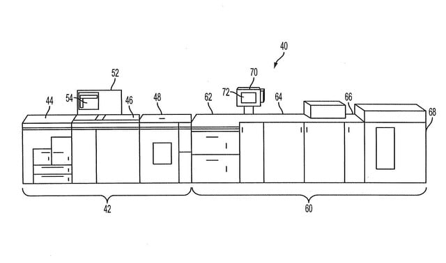
and, the print line 60 includes a feeder 62 , a multi-colorant marking engine 64 , a merge and transport unit 66 and a finishing unit 68 .
プリントライン60は給紙装置62、多色カラーマーキングエンジン64、合流移送ユニット66、及び仕上げユニットであるフィニッシングユニットであるフィニッシャ68を備える。
A controller 70 is provided with a graphical user interface 72 provided thereon;
コントローラ70はその上部にグラフィカルユーザインタフェース72を備えて設けられ、
and, the controller 70 may include the digital front end (DFE) for the marking engine 66 .
コントローラ70はマーキングエンジン64のためのデジタルフロントエンド(DFE)を備えてもよい。