


Ethernetシールドのテストを兼ねて、単純なローカルネットワーク用のWebサーバを作ってみました。
Arduino基板のピンヘッダーにEthernetシールドを接続し、LANケーブルで接続するだけでOKです。
テストのためのネットワーク構成


Arduinoには簡単にシールドが利用できるように、サンプルスケッチが用意されていますのでこれを利用します。
File→Example→Ethernet→WebServer を選択し、IDEに取り込みます。
PCでブラウザを開き、EthernetシールドのIPアドレスにアクセスすると、Arduinoの「Analog0」から「Analog5」までの入力電圧を読み取るスケッチになっています。
サンプルスケッチ
/*
Web Server
A simple web server that shows the value of the analog input pins.
using an Arduino Wiznet Ethernet shield.
Circuit:
* Ethernet shield attached to pins 10, 11, 12, 13
* Analog inputs attached to pins A0 through A5 (optional)
created 18 Dec 2009
by David A. Mellis
modified 4 Sep 2010
by Tom Igoe
*/
#include
#include
// Enter a MAC address and IP address for your controller below.
// The IP address will be dependent on your local network:
byte mac[] = { 0x90, 0xA2, 0xDA, 0x00, 0x48, 0xC6 };
IPAddress ip(192,168,1, 90);
// Initialize the Ethernet server library
// with the IP address and port you want to use
// (port 80 is default for HTTP):
EthernetServer server(80);
void setup()
{
// start the Ethernet connection and the server:
Ethernet.begin(mac, ip);
server.begin();
}
void loop()
{
// listen for incoming clients
EthernetClient client = server.available();
if (client) {
// an http request ends with a blank line
boolean currentLineIsBlank = true;
while (client.connected()) {
if (client.available()) {
char c = client.read();
// if you've gotten to the end of the line (received a newline
// character) and the line is blank, the http request has ended,
// so you can send a reply
if (c == '\n' && currentLineIsBlank) {
// send a standard http response header
client.println("HTTP/1.1 200 OK");
client.println("Content-Type: text/html");
client.println();
// output the value of each analog input pin
for (int analogChannel = 0; analogChannel < 6; analogChannel++) {
client.print("analog input ");
client.print(analogChannel);
client.print(" is ");
client.print(analogRead(analogChannel));
client.println("br />");
}
break;
}
if (c == '\n') {
// you're starting a new line
currentLineIsBlank = true;
}
else if (c != '\r') {
// you've gotten a character on the current line
currentLineIsBlank = false;
}
}
}
// give the web browser time to receive the data
delay(1);
// close the connection:
client.stop();
}
}
赤の太字の部分が修正した部分です。
MACアドレスはEthernetシールド個々に異なるアドレスで、本体の裏面にシールで表示されたアドレスを使用します。

IPアドレスは現時点でネットワークで使用されていないアドレスを使います。今回は192,168,1,90としました。
MACアドレス、IPアドレスともスケッチに入力するときは「,」で区切ります。
スケッチをコンパイルし異常なければ、Arduinoにアップロードします。
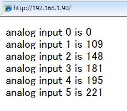
アップロードが完了したらPCでWebブラウザでIPアドレスにアクセスします。

0から5までのアナログポートに値が表示されますが、アナログポートには何も接続されていないのでランダムな値となります。

試しに「アナログ0~5」の各端子をジャンプワイヤーでグランドに接続し、接続した端子の値が「0」になれば読み取りが正常です。

Analog0をグランドと接続したときの表示
今回は特に関係ありませんが!!
Ethernetシールドは、SPI経由でArduinoと接続します。SPI接続ピンは、10,11,12および13ピンを使っています。
また、最近のEthernetシールドはボード上にマイクロSDカードを持っていて、デジタル4ピンはSDカードのスレーブセレクトピンを制御するため使用されていて、これらのピンは使用できなくなります。


※コメント投稿者のブログIDはブログ作成者のみに通知されます