下手の横好きのスクラップブック!!

下手の横好きの、いろいろな記録です。
電子工作・PIC・Arduino・太陽光発電・写真などetc

Arduino・Ethernetシールドをテストする(3) マイクロSDカードにデータを保存

2012-03-29 | Arduino

Ethernetシールドには、マイクロSDカードが実装できるようになっておりますので、今回はそれ利用してデータを保存してみます。
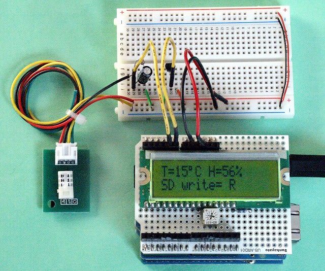
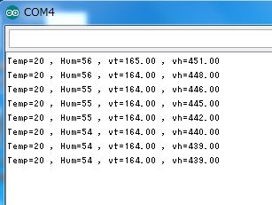
前回使った装置にLCDディスプレイを追加して、データを見えるようにします。さらにSerial Monitor で各データの確認ができるスケッチにしました。
センサー部分は前回のままですが、Arduino、Ethernetシールド、LCDシールドの3階建てになります。
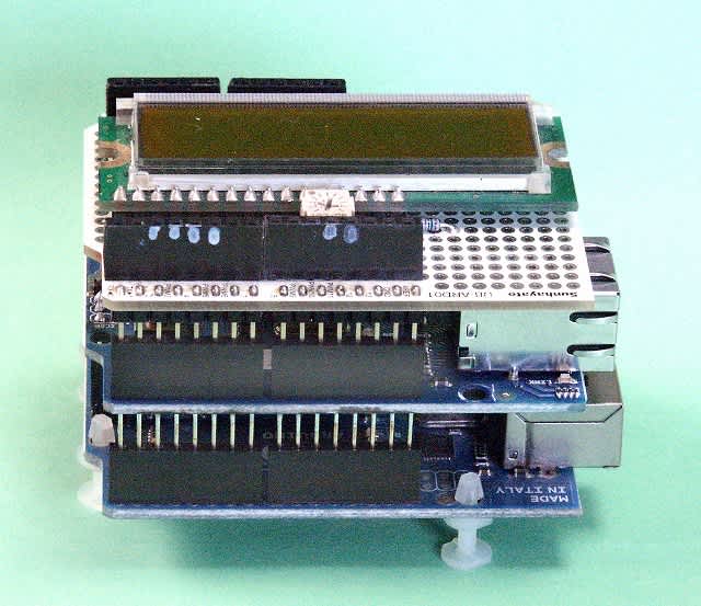
LCDディスプレイはEthernetのピンと重ならないように配線を変更しました。


全体の配線
スケッチ

#include <LiquidCrystal.h>
#include <SD.h>
 
const int chipSelect = 4;
float v = 5;
float vt = 0;
float vh = 0;
int Temp = 0;
int Hum = 0;
LiquidCrystal lcd(2,3,8,5,6,7);

float sen0 = 0;
float sen1 = 0;

void setup()
{
  Serial.begin(9600);
lcd.begin(16,2);
lcd.clear();
if (!SD.begin(chipSelect)) {
lcd.print("card failed, or not present");
return;
}
else {
lcd.print("card ON ");

void loop ()

sen0 = analogRead(0);
vt = sen0;
sen1 = analogRead(1);
vh = sen1;
Temp = (( vt *  0.00489 )- 0.6) * 100;
Hum = ( vh * 0.00489 * 30.855 ) -11.504;

Serial.print("Temp=");
Serial.print(Temp);
Serial.print(" , Hum=");
Serial.print(Hum);
Serial.print(" , vt=");
Serial.print(vt);
Serial.print(" , vh=");
Serial.println(vh);

lcd.clear();
lcd.print("T=");
lcd.print(Temp);
lcd.write(0xDF);
lcd.print("C");

lcd.setCursor(7,0);
lcd.print("H=");
lcd.print(Hum);
lcd.print("%"); 

File dataFile = SD.open("datalog.txt", FILE_WRITE);
if (dataFile) { 

dataFile.print("Temp,");
dataFile.print(Temp);
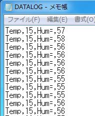
dataFile.print(",Hum=,");
dataFile.println(Hum);

dataFile.close();
lcd.setCursor(0,1);
lcd.print("SD write=");

lcd.setCursor(10,1);
lcd.print("R");
}
else {
lcd.print("error opening datalog.txt");
}

delay(60000);
}

 Serial Monitor確認画面
 
SDカードに保存されたデータ

データをエクセルに取り込みグラフ作成
 

コメント
  • X
  • Facebookでシェアする
  • はてなブックマークに追加する
  • LINEでシェアする

Arduino・Ethernetシールドをテストする(2) ネットワークで温度・湿度を見る

2012-03-26 | Arduino

前回使ったスケッチを少し変更して、温度と湿度をネットワークを介して見れるようにしてみます。

温度センサー
温度センサーはLM61を使いAnalog(0)へ接続します。
換算式は 温度 = ((analogRead(0)*0.00489)-0.6)*100を使います。

湿度センサー
湿度センサーは HSM20Gを使いAnalog(1)へ接続します。HSM20Gは温度と湿度の両方が読み取れますが、今回は湿度の方だけ使用しました。
湿度の出力特性と配線は次のようになっています。


湿度への換算式は  湿度(%)= (analogRead(1)*0.00489*30.855)-11.504としました。

配線

スケッチ
スケッチは以下の部分を赤の太字のように書き換えます。

  // output the value of each analog input pin
          for (int analogChannel = 0; analogChannel < 6; analogChannel++) {
            client.print("analog input ");
            client.print(analogChannel);
            client.print(" is ");
            client.print(analogRead(analogChannel));
            client.println("");


/*
  Web Server
 
 A simple web server that shows the value of the analog input pins.
 using an Arduino Wiznet Ethernet shield.
 
 Circuit:
 * Ethernet shield attached to pins 10, 11, 12, 13
 * Analog inputs attached to pins A0 through A5 (optional)
 
 created 18 Dec 2009
 by David A. Mellis
 modified 4 Sep 2010
 by Tom Igoe
 
 */

#include
#include

// Enter a MAC address and IP address for your controller below.
// The IP address will be dependent on your local network:
byte mac[] = { 0x90, 0xA2, 0xDA, 0x00, 0x48, 0xC6 };
IPAddress ip(192,168,1, 90);

// Initialize the Ethernet server library
// with the IP address and port you want to use
// (port 80 is default for HTTP):
EthernetServer server(80);

void setup()
{
 
  // start the Ethernet connection and the server:
  Ethernet.begin(mac, ip);
  server.begin();
}

void loop()
{
  int temp = 0;//追加
  int hum = 0;//追加
 
  
  // listen for incoming clients
  EthernetClient client = server.available();
  if (client) {
    // an http request ends with a blank line
    boolean currentLineIsBlank = true;
    while (client.connected()) {
      if (client.available()) {
        char c = client.read();
        // if you've gotten to the end of the line (received a newline
        // character) and the line is blank, the http request has ended,
        // so you can send a reply
        if (c == '\n' && currentLineIsBlank) {
          // send a standard http response header
          client.println("HTTP/1.1 200 OK");
          client.println("Content-Type: text/html");
          client.println();


      //スケッチ変更部分
            temp = ((analogRead(0)*0.00489)-0.6)*100;
            hum = (analogRead(1)*0.00489*30.855)-11.504;
            client.print("Temp = ");
            client.print(temp);
            client.print("deg");
             client.println("");
            client.print("Hum = ");
            client.print(hum);
            client.print("%");       
            client.println("");
            
          
          break;
        }
        if (c == '\n') {
          // you're starting a new line
          currentLineIsBlank = true;
        }
        else if (c != '\r') {
          // you've gotten a character on the current line
          currentLineIsBlank = false;
        }
      }
    }
    // give the web browser time to receive the data
    delay(1);
    // close the connection:
    client.stop();
  }
}


アップロードが完了したらPCのWebブラウザでIPアドレスにアクセスすると、温度と湿度をネットワークを介して見ることが出来ます。


コメント
  • X
  • Facebookでシェアする
  • はてなブックマークに追加する
  • LINEでシェアする

Arduino・ Ethernetシールドをテストする

2012-03-24 | Arduino

Ethernetシールドのテストを兼ねて、単純なローカルネットワーク用のWebサーバを作ってみました。
Arduino基板のピンヘッダーにEthernetシールドを接続し、LANケーブルで接続するだけでOKです。

テストのためのネットワーク構成


Arduinoには簡単にシールドが利用できるように、サンプルスケッチが用意されていますのでこれを利用します。
File→Example→Ethernet→WebServer を選択し、IDEに取り込みます。
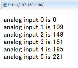
PCでブラウザを開き、EthernetシールドのIPアドレスにアクセスすると、Arduinoの「Analog0」から「Analog5」までの入力電圧を読み取るスケッチになっています。

サンプルスケッチ
/*
  Web Server
 
 A simple web server that shows the value of the analog input pins.
 using an Arduino Wiznet Ethernet shield.
 
 Circuit:
 * Ethernet shield attached to pins 10, 11, 12, 13
 * Analog inputs attached to pins A0 through A5 (optional)
 
 created 18 Dec 2009
 by David A. Mellis
 modified 4 Sep 2010
 by Tom Igoe
 
 */

#include
#include

// Enter a MAC address and IP address for your controller below.
// The IP address will be dependent on your local network:

byte mac[] = { 0x90, 0xA2, 0xDA, 0x00, 0x48, 0xC6 };

IPAddress ip(192,168,1, 90);

// Initialize the Ethernet server library
// with the IP address and port you want to use
// (port 80 is default for HTTP):
EthernetServer server(80);

void setup()
{
  // start the Ethernet connection and the server:
  Ethernet.begin(mac, ip);
  server.begin();
}

void loop()
{
  // listen for incoming clients
  EthernetClient client = server.available();
  if (client) {
    // an http request ends with a blank line
    boolean currentLineIsBlank = true;
    while (client.connected()) {
      if (client.available()) {
        char c = client.read();
        // if you've gotten to the end of the line (received a newline
        // character) and the line is blank, the http request has ended,
        // so you can send a reply
        if (c == '\n' && currentLineIsBlank) {
          // send a standard http response header
          client.println("HTTP/1.1 200 OK");
          client.println("Content-Type: text/html");
          client.println();

          // output the value of each analog input pin
          for (int analogChannel = 0; analogChannel < 6; analogChannel++) {
            client.print("analog input ");
            client.print(analogChannel);
            client.print(" is ");
            client.print(analogRead(analogChannel));
            client.println("br />");
          }
          break;
        }
        if (c == '\n') {
          // you're starting a new line
          currentLineIsBlank = true;
        }
        else if (c != '\r') {
          // you've gotten a character on the current line
          currentLineIsBlank = false;
        }
      }
    }
    // give the web browser time to receive the data
    delay(1);
    // close the connection:
    client.stop();
  }
}


赤の太字の部分が修正した部分です。
MACアドレスはEthernetシールド個々に異なるアドレスで、本体の裏面にシールで表示されたアドレスを使用します。


IPアドレスは現時点でネットワークで使用されていないアドレスを使います。今回は192,168,1,90としました。
MACアドレス、IPアドレスともスケッチに入力するときは「,」で区切ります。


スケッチをコンパイルし異常なければ、Arduinoにアップロードします。

アップロードが完了したらPCでWebブラウザでIPアドレスにアクセスします。


0から5までのアナログポートに値が表示されますが、アナログポートには何も接続されていないのでランダムな値となります。


試しに「アナログ0~5」の各端子をジャンプワイヤーでグランドに接続し、接続した端子の値が「0」になれば読み取りが正常です。


Analog0をグランドと接続したときの表示


今回は特に関係ありませんが!!
Ethernetシールドは、SPI経由でArduinoと接続します。SPI接続ピンは、10,11,12および13ピンを使っています。

また、最近のEthernetシールドはボード上にマイクロSDカードを持っていて、デジタル4ピンはSDカードのスレーブセレクトピンを制御するため使用されていて、これらのピンは使用できなくなります。


コメント
  • X
  • Facebookでシェアする
  • はてなブックマークに追加する
  • LINEでシェアする

2チャンネルLED温度計が故障

2012-03-06 | 電子工作・PIC

以前にキットで製作した2チャンネルLED温度計を、外気温度を計るために庭に設置していたところ、今朝になって片方(右側)の表示にエラーが発生しました。
表示は「Err1」で、マニュアルで調べたところ「センサーのマイナス端子とDQ端子がショートしている」と云うことです。
たぶん昨夜来の雨でセンサー部分に水分が侵入したのではないかと考えられます。防水加工に不備があったのかも!!
とりあえず、該当ののセンサーを取り外し片方のみで運転中です


コメント
  • X
  • Facebookでシェアする
  • はてなブックマークに追加する
  • LINEでシェアする

我が家の太陽光発電 2012年2月の発電量

2012-03-03 | 太陽光発電

2月の発電量は例年積雪の影響で少なくなりますが、今年は前年よりさらに低下してしまいました。
日照時間は144.3時間で平年比113%  昨年比111.4%と多くなっております。
降水日数、降雪深さ、最深積雪はいずれも平年より低く、本来なら発電量が増えるはずですが何故か低下しております。
平均気温が平年差 -2.0℃で融雪が進まなかったことと、太陽電池モジュールの劣化が影響していると思われます。


コメント
  • X
  • Facebookでシェアする
  • はてなブックマークに追加する
  • LINEでシェアする