少年カメラ・クラブ

子供心を失わない大人であり続けたいと思います。

EFHW Experiment on Counterpoise Height

2017-05-21 16:49:06 | アマチュア無線

The matching box made this time is a simple design tuning circuit consisting  a variable capacitor and a troidal core with two sets of coils, 3 truns in primary and 28 turns in secondary. The two coils are not connected each other but the connection can be cotrolled by a switch equipped on the box.

I brought this to a nearby park to test the box and EFHW antenna performance. The antenna wire used was 7.85m long copper wire. This is very close to 0.95 times a half wavelength of 18MHz, which is 7.91m.

Then, the vertically raised wire was connected with the matching box, this time the switch is in "Close"position meaning the primary and secondary coils are connected. The transimtter connected was FT817ND with a 2m long co-ax 3D2V cable. Output power was 5W with a Li-po battery.

Controlled parameter this time was the height of the counterpoise. A 6 mm wide tape measure was used as counterpoise in this experiment, then height of the counterpoise was changed. Tuning of the matching box was done every time counter poise height was changed with a counterpoise length of 2.8m.

Virtually no SWR change was observed when counterpoise length was changed. It is consistent from the previous experiment that co-ax cable is working partially as counterpoise. Common mode current was measured at each conditions.

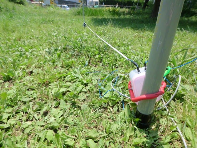
The height was changed from 1.7m to 0.1m from the ground. Regardless of the height, common mode current reduces at counterpoise lenth at around 2.8-3m. More energy should be radiated from the antenna at the point.


When height was 1.7m, the "resonating" characterisitics was sharper, but it was getting less sharper with lower counterpoise hight. I am not sure why this to happen. It is obvious that capacitive coupling between counterpoise and ground is getting larger, and it should explain this phenomenon. One thing for sure is that the counterpoise has some meaning even when shielding of the cable is working as counterpoise.

I will try the same experiment with no connection between primary and secondary coils.


EFHW Influence on Cable Width

2017-05-06 14:58:15 | アマチュア無線

18MHzのEFHW。チューナーは1次2次接続タイプ。カウンターポイズとして使ったメジャーの幅は6㎜と18㎜。明らかに幅の広いカウンターポイズを使った方が共振点がカウンターポイズの短い方にシフトした。

The resonant point shifted to the shorter counter poise legth when wider counter poise was used.


Common Mode Current of EFHW

2017-05-06 14:33:38 | アマチュア無線

18MHzのEFHW。チューナーは1次と2次がつながっている。

ケーブルの長さを2mと5mに取り換えてみた。いずれの場合も3mくらいでIcは最小になるが、ケーブルが短い時の方が急峻なディップが見られる。ケーブルの長さがコモンモード電流に大きく影響することが確認された。

A comparison of common mode current on cable length. Ic dipped sharpler when shorter cable was used. Cable length has a large influence on common mode current.


EFHW SWR With An Isolated Tuner

2017-05-06 14:05:15 | アマチュア無線

EFHWアンテナの実験の続編。以前はコイルの1次と2次がつながったデザインのチューナーで実験したが、今回は1次と2次が絶縁されたものでテスト。50㎝のカウンターポイズでチューニングを取った状態で徐々にカウンターポイズを伸ばしてみた。カウンターポイズが長くなると少しずつSWRの最小値の周波数が低くなり、同時にブロードな特性になった。前回と異なり、明らかにカウンターポイズの長さがアンテナの共振特性に影響を与えていることがわかった。JL1NIE局と翔馬君に感謝。
Another EFHW antenna experiment. This time, I used a EFHW tuner with secondary isolation with cable shielding. Antenna was tuned with CP=0.5m at around 18MHz first. Then, CP length were gradually increased. The change in CP length apparently influenced the resonat perfomance. The SWR minimum was moved to lower frequency as CP length increased.It is a quite contrast with the data obtained with the EFHW tuner with no shielding isolation. TNX JL1NIE and Shoma.


EFHW SWR With An Isolated Tuner

2017-05-06 14:02:21 | アマチュア無線

18.0MHzでインピーダンスの虚部がゼロになるように(つまり共振)調整したときのSWR特性。CP=1.1mくらいまでは、いい感じのSWR特性なのだが、そこを超えると急におかしな挙動を示した。共振イコールSWR=1ということではない。どういう風に理解すればいいんだろうね。
The tuner was set to a resonant (i.e. X=0) at 18.0MHz before SWR curves were measured. SWR was minimized at the resonant when CP length was 1.1m or less, but it drifted to higher frequencies when CP was longer. What does it mean? Interesting!


Common Mode Current of EFHW

2017-05-06 13:49:11 | アマチュア無線

1次と2次がつながったチューナーでの実験。

18MHz用のEFHWアンテナの給電点を1.6mとして、CP=0.5mでチューナーを調整18.08MHzでSWRはほぼ1.0に。給電点に0.5mのワイヤーをつなげて、その先に6㎜幅の金属メジャーを接続、様々な長さのCPでのコモンモード電流を計測した。リグはFT-817NDで5W出力。同軸長は2m(3D2V)

CPを一本と2本の時のコモンモード電流の大きさを計測したところ、いずれも2.8mくらいの長さのところで共振のようなディップを観測した。明らかに2本の方がシャープにディップした。(グラフ中のCP#1とCP#2)

片方のCPの長さを2.8mに固定して他方のCPの長さを変えてみると、極端なディップはなくなるも3m前後で最小値を示した。

因みに2.8mのCP2本の角度を変えてみると

0°(同じ方向)=12mA

90°=6.4mA

180°=5mA

となりやはり広げた方が良さそう。


Common mode current (Ic) influence on counter poise length. Ic sharply decreased at counter poise length of c.a. 2.8m. Feed point hight was 1.6m, and SWR was set to 1.0 at 18.08Mhz with a counter poise of 0.5m and a tuer with primary-secondary connection. FT-817ND was used to make 5W out put.Cable was 2m 3D2V.

Ic was dipped at its length of 2.8m. The dip was getting sharper when two CP were used. It may be worth note that the dip was getting less sharper when one CP lentgh was fixed at 2.8m.

Influence of angles between two CP was also examined. Wider angle seemed to be better in terms of common monde current.