gooブログはじめました!

写真付きで日記や趣味を書くならgooブログ

HOW TO PERFORM VCI CONNECTION BY AUTEL MK908P MK908 DIAGNOSTIC TOOL

2021-02-21 11:26:14 | 日記

After the VCI device is properly connected to the vehicle, the Power
LED on the VCI device illuminates solid green light, and is ready to
establish communication with the MaxiCOM MK908P/MK908 display tablet.


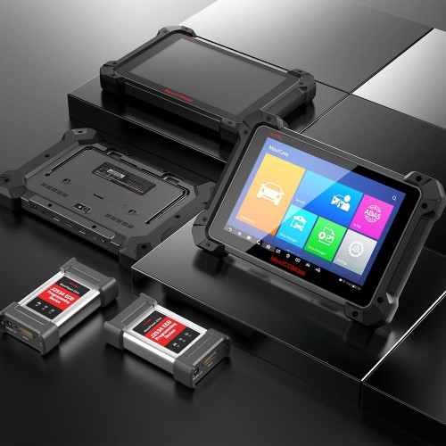
The Wireless Diagnostic Interface, which comes with the MaxiCOM tool
kit, supports 2 communication methods with the MaxiCOM display tablet:
BT and USB.


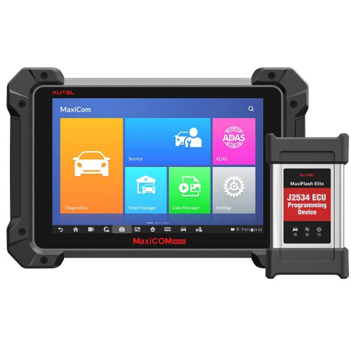
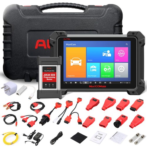
The J2534 ECU Programming Device, which comes with the MaxiCOM Pro
tool kit, supports 2 communication methods with the MaxiCOM display
tablet: BT, and USB.


autel-mk908p-mk908-vci-connection-succeed-1
autel-mk908p-mk908-vci-connection-succeed-2


First Main Step: Pairing Up via BT


Among all methods, BT pairing is recommended as the first choice for
the25 communication between the MaxiCOM display tablet and the VCI
device. The working range for BT communication is about 210 feet (70 m);
this means you can perform vehicle diagnosis freely around the workshop
with greater convenience.


If you use more than one VCI device to connect to the test vehicles
when customers are many, you can perform vehicle diagnosis on various
vehicles conveniently, by pairing the MaxiCOM display tablet separately
to each of the VCI devices connected to the different test vehicles, via
BT, without the need to repeat the plugging and unplugging procedure,
which is unavoidable through traditional wired connection, thus saves
you more time and provides more efficiency.


You need to pair up the MaxiCOM display tablet with the VCI device via BT:


If not already done, power up the MaxiCOM display tablet.
Select the VCI Manager application from the MaxiCOM Job Menu.
When the VCI Manager application is opened, the device automatically
starts scanning for available VCI devices around for BT pairing. The
found devices are listed in the Setting section on the right side of the
screen.
Depending on the VCI type you use, the device name may display as Maxi
suffixed with a serial number. Select the required device for pairing.


When paring is successfully done, the connection status displayed to the right of the device name is shown as Paired.


Wait for a few seconds, and the VCI button on the system
Navigation bar at the bottom of the screen shall display a green tick
icon, indicating the display tablet is connected to the VCI device, and
is ready to perform vehicle diagnosis.


Important message:


If no VCI device is found, this may indicate that the signal strength
of the transmitter is too weak to be detected. In this case try to get
closer to the device, or reposition the VCI device, and remove all
possible objects that causes signal interference. When these are done,
tap the Scan button at the top right corner to start searching again


Second Main Step: USB Cable Connection


The USB cable connection is a simple and quick way to establish26
communication between the MaxiCOM display tablet and the VCI device.
After properly connecting the USB cable from the tablet to the VCI
device, the VCI navigation button at the bottom bar of the screen shows a
green tick icon in a few seconds, and the USB LED on the VCI device
illuminates solid green light, indicating the connection between the
devices is successful.


Keep this in mind:


Since the USB connection provides the most stable and fastest
communication, it is highly recommended to apply this communication
method when operating ECU programming or coding. When all the two
communication methods are applied at the same time, the unit’s system
will use the USB communication as the default priority


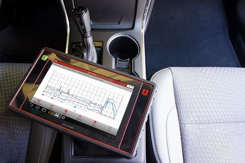
Very well. You’ve finished VCI connection by MaxiCOM MK908P/MK908 diagnostic platform to connect the vehicle with the unit.


It is now ready to perform vehicle diagnosis. Awesome!


autel-mk908p-mk908-vci-connection-succeed-3


That’s all. Thanks so much for sharing your time with us!


SD Connect configuration Road24h mode. Setup connection

2021-02-21 11:24:06 | 日記


SD Connect configuration Road24h . Setup and connection via LAN cable and Wi-Fi direct connection.
1. Configuration Road24h mode for Windows XP.
2. Configuration Road24h  mode for Windows 7.


1 . SD Connect configuration Road24h mode for Windows XP.
1.1. Make the configuration of the laptop for the LAN connection.


Connect the device to power supply and to the laptop by cable.


Make the LAN settings connections: network connections/local area
connection/properties/TCP/IP in accordance with the screenshot below:


SD-Connect-configuration-Road24h-mode-Setup-connection-1


Everywhere click OK, the connection is established :


SD-Connect-configuration-Road24h-mode-Setup-connection-2


The device is ready for operation via the lan connection.


1.2. Make the configuration of the laptop for the WiFi connection.


Go to network connections/wireless network/properties/TCP/IP


Custom WiFi connection for the computer :


SD-Connect-configuration-Road24h-mode-Setup-connection-3


Click on all windows OK.


1.3. Create a wireless network Road24h.


Open the wireless networks list. Click “change the order of preferred
networks” in the new window create a network to connect to by default
Road24h. Enter the settings according to the screenshot:


SD-Connect-configuration-Road24h-mode-Setup-connection-4


Confirm in the last window OK. See the list of preferred networks, a
network Road24h. Click properties, note the check box automatically
connect, confirm OK:


SD-Connect-configuration-Road24h-mode-Setup-connection-5


We can see that our network has received the status of
“automatically”. Click OK. Check that the created network in the
networks list:


SD-Connect-configuration-Road24h-mode-Setup-connection-6


1.4. Make configuration of a multiplexer for a wireless connection Wi-Fi.


The appliance must be connected by cable and connection on a local network.


Go to SDconnectControl (lower right corner of your desktop) click in
the system tray SDNC. Click “configuration” and confirm “Yes”:


SD-Connect-configuration-Road24h-mode-Setup-connection-7


Select the tab “MUX” and “register/configure”:


SD-Connect-configuration-Road24h-mode-Setup-connection-8


Opens the configuration window of the multiplexer.


Make WiFi network settings for multiplexer in accordance with screenshot :


SD-Connect-configuration-Road24h-mode-Setup-connection-9


The network key is 26 characters. In this case, 26 English letters “a” in lowercase.


Click start and should see this result :


SD-Connect-configuration-Road24h-mode-Setup-connection-10


Disconnect the LAN cable. Now, when you turn on the multiplexer,
Wi-Fi connection will be established automatically. To make sure there
is communication between multiplexer and laptop is possible in the
selection of the multiplexer, click the “Test signal”:


SD-Connect-configuration-Road24h-mode-Setup-connection-11


2. SD Connect configuration Road24h mode for Windows 7.
2.1. Make the configuration of the laptop for the LAN connection.


The power supplied to the multiplexer and connected to the computer via LAN cable.


Go : control Panel/control Center network and sharing/Change adapter
settings/local area Connection. Enter the LAN settings of the connection
according to the picture :


SD-Connect-configuration-Road24h-mode-Setup-connection-12
Confirm all Windows with “OK”.


The connection cables are installed, which shows its icon in system tray:


SD-Connect-configuration-Road24h-mode-Setup-connection-13


2.2 Enter the settings of the wireless WiFi adapter in the computer.


Go: control Panel/control Center network and sharing/Change adapter
settings/Wireless network connection. Make settings according to the
screenshot:


SD-Connect-configuration-Road24h-mode-Setup-connection-14
SD-Connect-configuration-Road24h-mode-Setup-connection-15


Confirm all Windows with “OK”. All the WiFi network settings entered in the computer.


2.3. Create network “Road24h” in the computer.


To do this, go to control Panel/control Center network and sharing/
Manage wireless networks/ Add / new connection computer — to-computer
/next. Enter the data according to the screenshot. Do not forget to put a
tick in the checkbox “Save settings for this network” :


SD-Connect-configuration-Road24h-mode-Setup-connection-16
SD-Connect-configuration-Road24h-mode-Setup-connection-17
SD-Connect-configuration-Road24h-mode-Setup-connection-18


Click “next”. Network “Road24h” created :


SD-Connect-configuration-Road24h-mode-Setup-connection-19


Close all Windows, check that the created network in the wireless
networks list. Our established network must have the status “Waiting for
connection” user :


SD-Connect-configuration-Road24h-mode-Setup-connection-20


2.4. Next, enter the configuration settings for the WiFi connection
in the multiplexer. Right-click in the system tray SDNC, in the context
menu, choose “Administration”. In the opened window select the tab
“Register/configure”. Enter settings according to the screenshot (the
key is arbitrary, any 26 characters, the same like for computer
settings) :


SD-Connect-configuration-Road24h-mode-Setup-connection-21


Click “Start”, the configuration is stored in the memory of the multiplexer, and as a result needs to obtain such a table :


SD-Connect-configuration-Road24h-mode-Setup-connection-22


The device is configured, close all Windows, LAN cable disconnected.


Then restart the multiplexer. During the boot process of the
multiplexer, the WiFi connection between the computer and the device
will be installed automatically. Its icon appears in the system tray
SDNC. open the selection window of the multiplexer. Right-click in the
system tray SDNC, in the context menu choose “Select”. In the opened
window select your multiplexer and confirm “Select”:


SD-Connect-configuration-Road24h-mode-Setup-connection-23


In this procedure the connection setup multiplexer SD Connect to work with Xentry OpenShell program under Windows 7 is finished.


A diagnostic system is ready for operation.


Further, the inclusion of a diagnostic system should be as follows:


Turn on the computer, the operating system boots.
Check in the list of networks network status “Road24h”. Status should be
“Waiting for connection” user, if not, click “Connect”, the network
status is changed to required.
Then turn on the multiplexer. Connection via Wi-Fi network should be installed automatically.


Restore ECU DeadKilled After Flashing with UNKN 0000 Error

2021-02-14 09:45:11 | 日記


For a beginner of BMW flashing/programming by E-sys software,sometime
you maybe find some control modules dead or killed without
communication,it show UNKN 0000 error.So here Obd2tool.com show you guide on how to restore it.More about BMW E-sys cases,please check it here: BMW Trouble Repair


Preparations:


BMW E-sys 3.33.0/3.32.1/3.30.01 Coding Software Free Download


Procedures:


After ECU dead,it show UNKN 0000 on E-sys,and it can’t be communicated


Now we need to edit SVT again to restore it.


Open below window,and click “Calculate” to locate SVT target file,and then click “Edit” button to edit


Open sub-options to locate dead ECU file


Right click “UNKN 0000” and click “Delete”,then save the modification


Click “Calculate” button marked with 5,and save it.


Check the four boxes with IBA file,and for other only 3 boxes checked


Access to forced flashing/programming status.


Then click “Start” button to programming,after then ECU will restore communication.


What is the difference between X431 v+ and the launch pad ll

2021-02-14 09:41:20 | 日記


Original Launch X431 PAD II new high-end Android professional diagnostic scan tool comes to replace X431 Pad I, X431 V (X431 Pro) and X431 V+ (X431 Pro3). X431 PAD II comes with dust and waterproof design (IP65),
including docking station for DBSCar, EasyDiag and golo Full system
diagnosis for more than 70 brands; access to all available vehicle
systems; coding, programming (key, immobilizer system) and service
reset.


Launch X431 Pad II vs. X-431 PAD vs. X431 V Pro vs. X431 V+


Conlusion:
launch pad ll is powerful than X431 V+
But X431 V+ cheaper than X431 PAD2.


What is the difference between X431 v+ and the launch pad ll

2021-02-13 17:15:47 | 日記


Original Launch X431 PAD II new high-end Android professional diagnostic scan tool comes to replace X431 Pad I, X431 V (X431 Pro) and X431 V+ (X431 Pro3). X431 PAD II comes with dust and waterproof design (IP65),
including docking station for DBSCar, EasyDiag and golo Full system
diagnosis for more than 70 brands; access to all available vehicle
systems; coding, programming (key, immobilizer system) and service
reset.


Launch X431 Pad II vs. X-431 PAD vs. X431 V Pro vs. X431 V+


Conlusion:
launch pad ll is powerful than X431 V+
But X431 V+ cheaper than X431 PAD2.