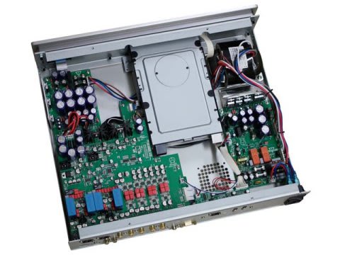
前回撮った、oppo BDP-95の内部写真です。

左上がDAC基盤に電源を供給している基盤ですが、3個の3端子レギュレーター(LM317×2、LM337)で電圧を作っています。これを置き換えてやれば、なにかしらの変化は起きそうです。

DAC基盤側のコネクタ
なんらかの保護回路のため、このDAC基盤が通電していないとシステムの電源が立ち上がらないので、動作させながら電圧を測ってみました。
VO+:+15.6V
VO-:-15.2V
+12.5V:+9.9V
OVP-TEST:+1.5V
?????
+12.5V表記で10Vなのが謎です。あと、DACの為にもうちょっと低い電圧を供給していると思ったのですが、どれも結構高めです。供給端子の直後にレギュレーターが入っているのもイヤな感じですね(手前で作って入れればいいのに)。
どうにもスッキリしないので、WEBをしばらくぐるぐるしていたのですが、こんなスレッドを見つけました。
Upgrading & modding new Oppos, BDP-93 & BDP-95
その中で、一番良くまとまっている電源関係の書き込みがコレです。
Let me explain very clearly how the stock 95 power supplies are: First there is unregulated plus and minus 21 volts (would have been nicer to configure the tranny for about plus and minus 18.5...for heat sake). On the separate power supply board there are three preregulators. A plus and minus 15 and a plus 9.74. All done with 317 and 337 regs. The power then goes to the output board where the plus and minus 15 go through another set of regs to make plus and minus 10 for the opamps (317 and 337 again). The plus 15 volt also feeds the two 3.3V regs for the analog part of each DAC. These regs are super reg types....that is, they use an opamp and a discrete pass device.....they are not monolythic regs. This is well thought out for a $1000 thang. The 9.7 Volt supply feeds all the "digital" supplies....the 1.2v and the 3.3v regs. The analog 3.3 Volt supply does feed the 54 meg oscillator (this should have been another reg for sure). Oppo is probably feeding the 3.3V analog supply off the plus 15 volt supply to keep it from seeing the noise on the digital supplies.
There are 3 preregs and 10 regulators on the output board. This is pretty darn serious for a $1000 unit that smokes most $3000 thangs out there. Yes, you can use more and better supplies and also up the frequency on the clock....but this is one hell of a nice machine for $1000.....in fact, its incredible what they give you. But of course, we are perfectionistic tweakers so we will do whatever we can to improve it. However, what Oppo did is pretty darn nice.
トロイダルコアトランスから供給されている21V(高すぎ!)から電源基盤上で±15V、10Vを作成し、DAC基盤に供給。そのあと以下のように使われるようです。
±15V → ±10V → オペアンプ(IV?)
±15V → 3.3V → DACアナログ部分、他
+10V → 3.3V、1.2V → DACデジタル部分
・・・・。結構このスレではoppoの設計についてボロクソ言われています。自分は素人ですが、確かにちょっとビミョーって感じがしますね。でも今回は元に戻せるようにいじるつもりなので、DAC基盤に入っちゃった後はどうしようもないです。電源基盤までを切り替えることにします。
左上がDAC基盤に電源を供給している基盤ですが、3個の3端子レギュレーター(LM317×2、LM337)で電圧を作っています。これを置き換えてやれば、なにかしらの変化は起きそうです。
DAC基盤側のコネクタ
なんらかの保護回路のため、このDAC基盤が通電していないとシステムの電源が立ち上がらないので、動作させながら電圧を測ってみました。
VO+:+15.6V
VO-:-15.2V
+12.5V:+9.9V
OVP-TEST:+1.5V
?????
+12.5V表記で10Vなのが謎です。あと、DACの為にもうちょっと低い電圧を供給していると思ったのですが、どれも結構高めです。供給端子の直後にレギュレーターが入っているのもイヤな感じですね(手前で作って入れればいいのに)。
どうにもスッキリしないので、WEBをしばらくぐるぐるしていたのですが、こんなスレッドを見つけました。
Upgrading & modding new Oppos, BDP-93 & BDP-95
その中で、一番良くまとまっている電源関係の書き込みがコレです。
Let me explain very clearly how the stock 95 power supplies are: First there is unregulated plus and minus 21 volts (would have been nicer to configure the tranny for about plus and minus 18.5...for heat sake). On the separate power supply board there are three preregulators. A plus and minus 15 and a plus 9.74. All done with 317 and 337 regs. The power then goes to the output board where the plus and minus 15 go through another set of regs to make plus and minus 10 for the opamps (317 and 337 again). The plus 15 volt also feeds the two 3.3V regs for the analog part of each DAC. These regs are super reg types....that is, they use an opamp and a discrete pass device.....they are not monolythic regs. This is well thought out for a $1000 thang. The 9.7 Volt supply feeds all the "digital" supplies....the 1.2v and the 3.3v regs. The analog 3.3 Volt supply does feed the 54 meg oscillator (this should have been another reg for sure). Oppo is probably feeding the 3.3V analog supply off the plus 15 volt supply to keep it from seeing the noise on the digital supplies.
There are 3 preregs and 10 regulators on the output board. This is pretty darn serious for a $1000 unit that smokes most $3000 thangs out there. Yes, you can use more and better supplies and also up the frequency on the clock....but this is one hell of a nice machine for $1000.....in fact, its incredible what they give you. But of course, we are perfectionistic tweakers so we will do whatever we can to improve it. However, what Oppo did is pretty darn nice.
トロイダルコアトランスから供給されている21V(高すぎ!)から電源基盤上で±15V、10Vを作成し、DAC基盤に供給。そのあと以下のように使われるようです。
±15V → ±10V → オペアンプ(IV?)
±15V → 3.3V → DACアナログ部分、他
+10V → 3.3V、1.2V → DACデジタル部分
・・・・。結構このスレではoppoの設計についてボロクソ言われています。自分は素人ですが、確かにちょっとビミョーって感じがしますね。でも今回は元に戻せるようにいじるつもりなので、DAC基盤に入っちゃった後はどうしようもないです。電源基盤までを切り替えることにします。