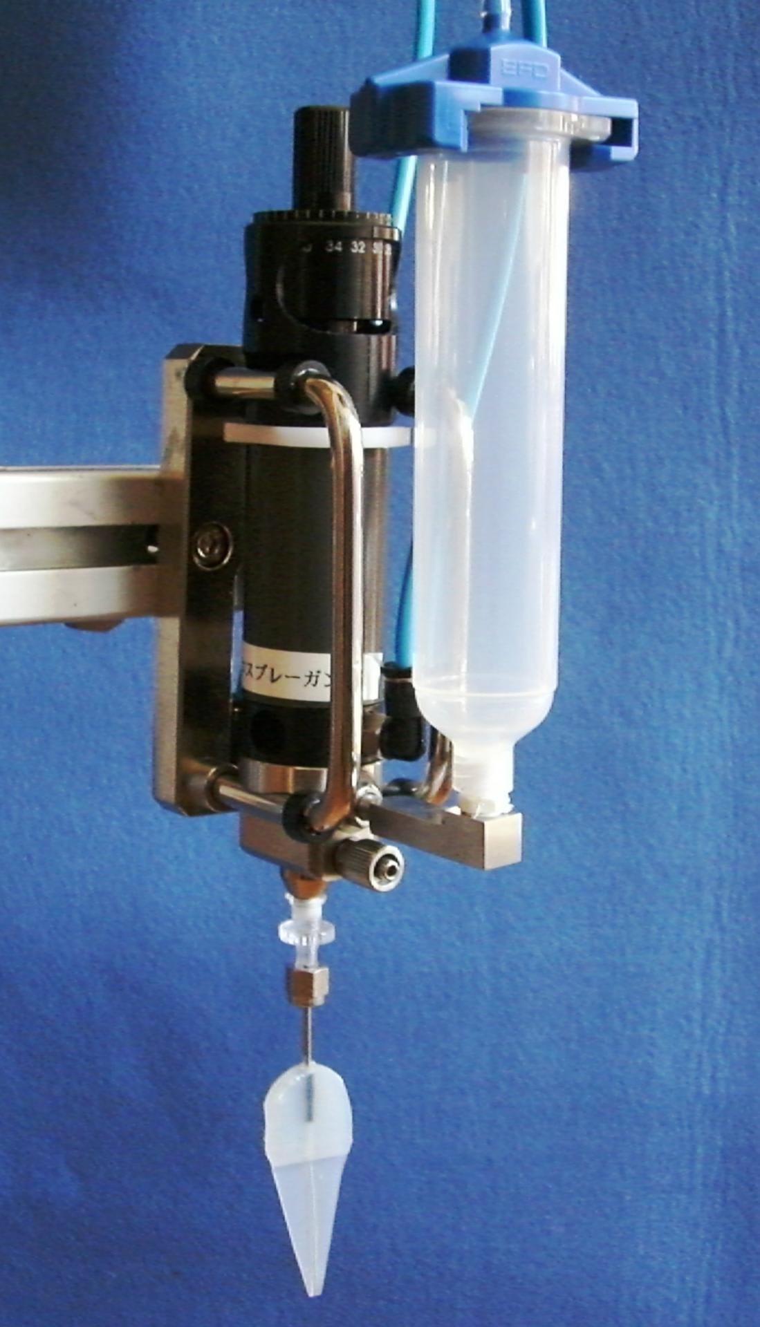
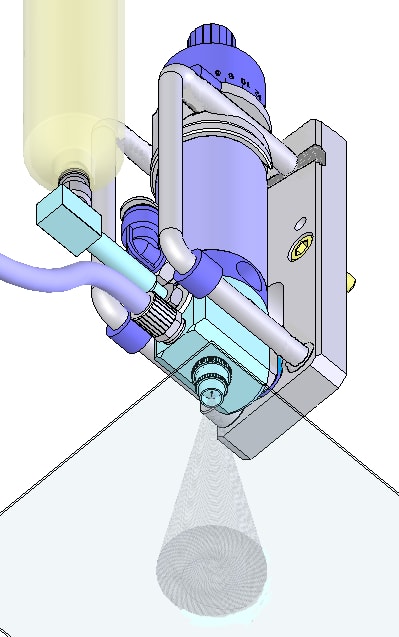
FS Type Micro Spray Gun's Ability ( Photo Resist Coating,Functional Coating,Conformal Coating)
This gun is used for thin film coating with solventborne coating material, dispersion coating material and waterborne material. This gun can spray nano-evenness coating with automatic gun to use 3 dimensions axis (X-Y-Z) robot driven by thin film coating software. This is a spray gun that circulates around the liquid that contains phosphor and is sprayed.
FS Micro Spray Gun Characteristics.
1)The flow rate adjustment of the slight quantity from 0.5g/min is possible. (max is about 20g/min.)
2)Coating film thickness can be adjusted to the 0.1μm~50μm (In case of photo resist coat) .
3)Small territory coating of 3~φ 8mm is possible.
4)Liquid use efficiency is very high in comparison with spinners. (50%-75 %)
5) It can be coated with the small quantity of about 5CC as well.
Application example.
1.Photo resist coating
2.Polyamide coating
3.Stick water film coating
4.Silver paste coating
5.Special adhesive coating
6.Others
(Japanese Patent & PCT Patent Pending)
URL:http://shimadaappli.com/