The optimum pattern width used by the Shimada Application* is explained below.
* Shimada Application is Appl. No.: 07/206,199 (Method for applying a moisture proof insulated coating to printed circuit boards using triangular or dovetail shaped liquid films emitted from a flat-pattern nozzle.) developed as a selective coating 30 years ago.
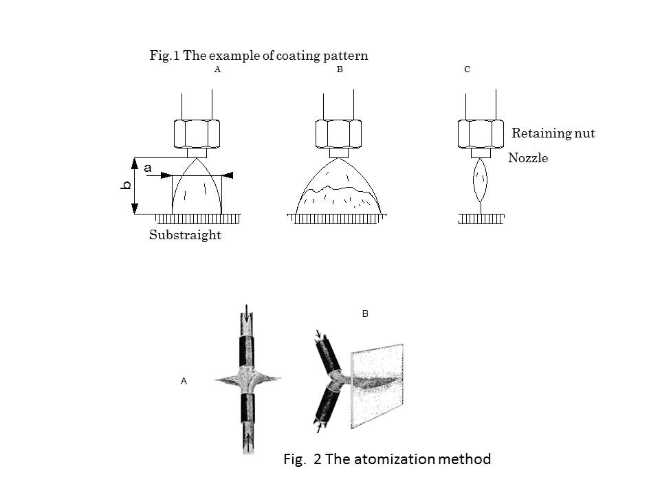
When coating liquid material with film coating application, it becomes three forms as shown in the above figure. It becomes relevant conditions that an upper portion touches a coated object from the nozzle location of max wide pattern width by A or C.
As for B, film formation is made by the nozzle peripheral part. After that, thread or scattering is seen in the shape of a particle. When it applies in the part by which film formation is carried out, a good film plane is not obtained.
In the liquid distribution in a pattern, liquid concentration starts this at the end, and the pattern central part becomes a fluid volume fall.
The state where distribution of the film in a film plane has the thin central part, and an end is deep remains.
Moreover, it is easy to come also out of scattering when coating liquid hits a coated object. (It influences with an angle with the coated object of a coating pattern end)
Since A becomes a proper coating condition as pattern formation, it needs to carry out a condition setup so that it may be set to A.
C state conditions have high viscosity, or are the result of producing, when what has the narrow type with few amounts of discharge or application width of a nozzle is selected.
Although the application can do C, film thickness is thick, does not have linearity and tends to produce that a bubble is moreover generated etc.
B is when application liquid has low viscosity and high fluid pressure.
Pattern width can be changed with a nozzle kind, nozzle distance, and liquid viscosity.
As standard effective application width:
a: Size (pattern width) 4-16 mm
b: Size (nozzle distance) It is 6- 20 mm.