Red Pitaya HAMLAB/SDR Transceiver and Measurement Equipments
ElectronicsDIY5 web shop
www.shop-online.jp/ElectronicsDIY5/
***********************************
情報更新
現在、HAMLabは、10W Model/100W modelがあります。(10W modelは実際には、20W出ますので、1kWアンプで押すと、200W運用も工夫しだいで可能です)
当初と比較し、Vector Network Analyzerや、Bode Analyzerが加わっています。
Windows10 Pro 64bit Windows Version 1809で基本動作を再確認致しました。
Welcome to the HAMlab user manual
https://hamlabdoc.readthedocs.io/en/latest/index.html


MDSを再測定してみました。(電源 Agilent E3631A使用/CV mode 13.80V)
@7MHz 500Hz BW
Preamp off>>>-118dBm
Preamp 6dB>>>-127dBm
Preamp 12dB>>>-123dBm(noise floor上昇で、MDS低下/unknown)
Preamp 18dB>>>-130dBm
Preamp 24dB>>>-134dBm
Preamp 30dB>>未測定(18dB段階で、880mAに消費電流が上昇したため)
おおむね、max -135dBmのスペックは満たしていると考えられます。
*******************************************************
プロトタイプ画像(画像と実際のフロントパネル構成は異なります)


PowerSDR HAMlab Edition(max 384kHz sampling rate)

*******************************************
RedPitaya HAMLAB SDR Transceiver 7MHz demo
https://www.youtube.com/watch?v=aHXQjBOElrs&feature=youtu.be
*******************************************

Using PowerSDR directly as the measurement equipment "Spectrascope".
10.000000000MHz Sinewave -30dBm

*******************************************
Oscilloscope and Signal Generator
IN1(OSC with 50ohm feed through terminater):CH1 10MHz Sinewave
OUT1(SigGen):10MHz Sinewace 200mVp-p/50ohm load(it means 400mVp-p/open)

********************************************
Spectrum Analyzer

********************************************
Logic Amalyzer:pro mode

I2C decoding

******************************************************************
The design has been altered from the first pre-order promotion.SDR is changed to MIC(LAN type 8Pins)/KEY/Phones like below.


***************************************************
Red Pitaya Hamlab has just been announced at Friedrichshafen Ham Radio 2016 expo. It is a dual-receiver dual-transmitter DDC/DUC HF/6m 10W SDR transceiver with extended measurement capabilities, based on the popular Red Pitaya development board.
The RF is converted to the digital domain with a LTC2145-14 125Msps 14-bit ADC (comparable to what an Icom IC-7300 uses, for example), so performance should be pretty good. Receiver coverage is 0-60MHz and +15dB preamp and -6/12/18dB attenuators are available for different levels of frontend gain settings.
The transmitter has currently 10W and is optimised for the 160m-6m bands. A higher power amplifier (100W, for example) can be integrated without much effort and the configuration makes it pretty easy to add external filters for the 472kHz or 137kHz bands.
The connection with the computer is realised via Ethernet. It is also possible to use an external physical controller with knobs, but the computer is still required for display, processing and advanced control.
The transceiver is compatible with various SDR software packages out there, such as PowerSDR, HDSDR, Gqrx, GNU Radio, GNU Radio Companion and Pothos. Even there are two transmitters available, we can assume only one can be used at one time with the output power amplifier.
But Red Pitaya Hamlab is much more than just a good SDR transceiver. It is also a dual-channel 50MHz oscilloscope, a dual-channel 62MHz bandwidth spectrum analyzer with 80dB dynamic range and an 8-channel logic analyzer. It can also be easily turned into an LCR meter, a Network Vector Analyzer and even more. All this is possible thanks to the Red Pitaya board and makes this a very useful equipment in any shack.
****************************************************
****************************************************
SDR specifications
Please find more info on the following link: http://wiki.redpitaya.com/index.php?title=HAMLAB
Receiver Architecture: direct sampling
Wideband Freq. Coverage: 0-60 MHz
RX Channels: 2
TX Channels: 2
Transmit Freq. Coverage: 80-10m amateur bands
Output power: 10W nominal
Preamplifiers/Attenuators: not available at the moment. Possibility of purchasing them later (are in development and will be available soon at an affordable price)
Required power supply: 12V/20A; not included in the price
Data transfer: Gigabit Ethernet, WIFI
Compatible with Power SDR, HDSPR, Gqrx, GNU Radio, GNU Radio Companion and Pothos
Oscilloscope specifications:
Input channels: 2
Bandwith: 50 MHz
Sampling rate: 125 Msps
Input range: +- 20V
Resolution: 14 bit
Imput impedance: 1MΩ/10pF
Oscilloscope probes: included
Works with Linux, Windows and MAC
Spectrum Analyzer Specifications:
Input channels: 2
Bandwith: 62 MHz
Dynamic range: 80dBm
Input noise level:<-119dBm/Hz
Works with Linux, Windows and MAC
Logic Analyzer Specifications:
Input channels: 8
Protocol decoders: SPI, UART, I2C
Sample rate: 125Msps
Logic levels: 2.5V/3.3V/5V
Probes: included
*********************************************************************
Vector Network Analyzer
http://pavel-demin.github.io/red-pitaya-notes/vna/
VNA Bridge(VNA module)が別途、必要で、HAMLabでも動作するだろうとの事です。

vna.exeは、red pitaya local IPでconnectする方法はすでにわかっています。
S11は、DUTに接続だけなので、すぐわかりますが、S21の測定などでの接続方法を聞いています。これは、マニュアルも必要だと思いますので、instructionがないか、確認中です。確認が進めば、当方でもVNA moduleを入手して、有用性を評価する予定です。
The VNA function is in progress.I will update the info here.
**********************************************
Bode Analyzer
こちらは、既に、firmware updateするだけで使えます。他の、Bode Plot同様、calibrationを行ってから、測定をします。
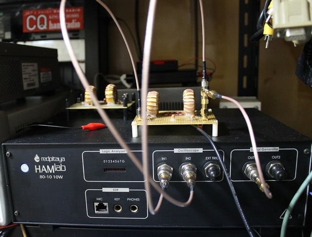
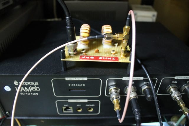
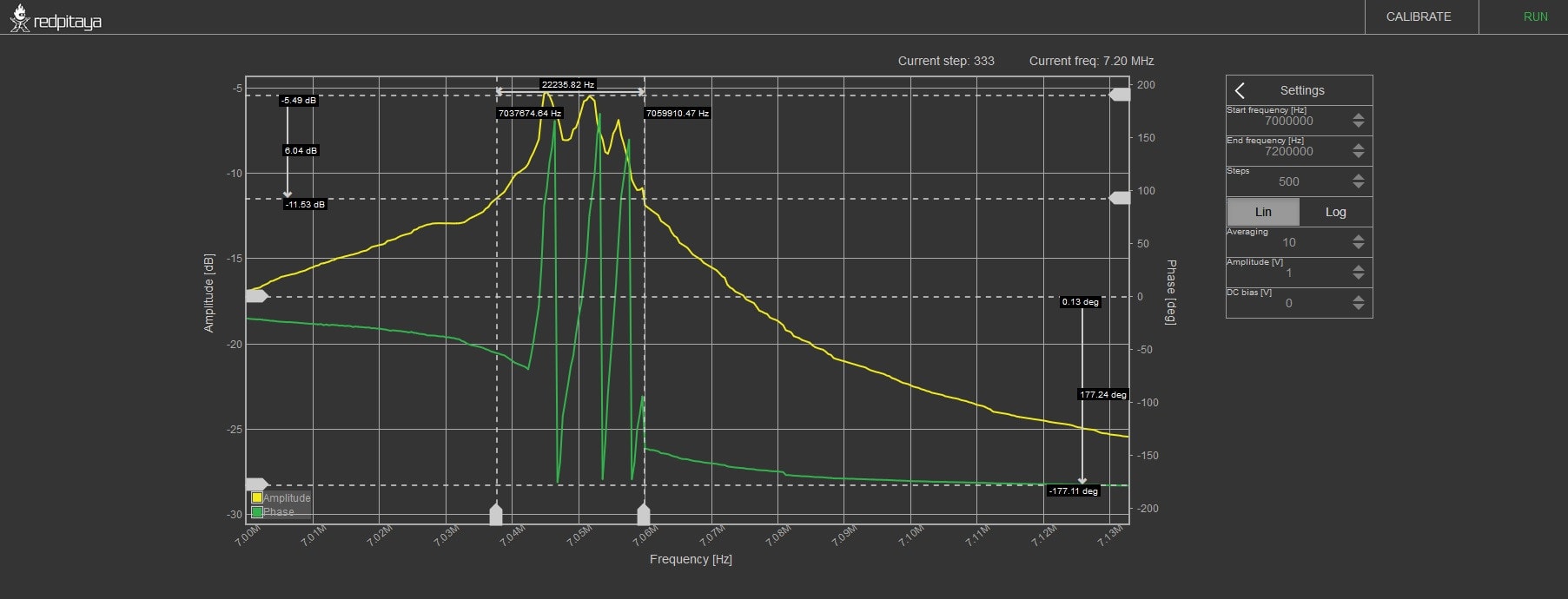
7MHz BPFの測定
周波数設定は、かなり自由にできます、たとえば、6.9MHz(6900000Hz)-7.3MHz (7300000Hz)で、Stepもどこまでかはまだ確認してませんが、512stepsにもできますし、1KHzごとのplottingのの400000steps(40万)にもでき、すごーく、時間がかかり、途中でやめました。LOLちょっと、まだ、insertion lossが、512stepでは、正確には測定できていません。(本来、-5.5dB)Bandwidthもやや広い測定値です。BW 100kHz BPFでは、精度が落ちるきらいがあります。もともと、なかった機能がただで追加されたので、そう文句は言えません。LOL動くかさえ、当初は使い方も説明が少なく、わからないぐらいだったので、まあ、これだけ動けば、まあまあ、満足は当方はしています。もう少し、条件を整えて、再評価したいと思います。
step設定、これがplottingに当たるようですが、その他 averageが、1-10で設定でき、これで、plotごとに平均を取り、測定をより正確にする工夫かと思います。Horizontal は、LIN/Log 切替えができ、通常、BPFの測定では、LINを選択します。Keysight 1000X seriesは、最近、いくつか、改善されたか、聞きましたが、FRA(Bode Plot)は、log表示だけのままでした。前はたった。10pointだけでしたが、今は 1-10 などごとに50pointに増えてるそうです。まあ、それでも少ないかなと思います。学生など教育向けなので、上位機種に比し、機能制限がありますね。
さて、このHAMLabのBode Analyzerなんですが、今後、細かいところをつめて改善されていくといいのではないかと感じています。calibrationは、100Hz-62MHぐらいまで、500stepで行います。LINか、Logか選択して、calibrationをかけます。calibration時の接続方法は簡単で、OUT1 をpower splitter などか、T分岐で、DUTを使わないで、IN1/IN2に接続します。今回、すべて、sma connectorを揃える事ができませんでしたが、できれば、sma cableで揃えて、しかも、同じ長さにしたり、気を使ったほうがいいようです。
Linear Calibration

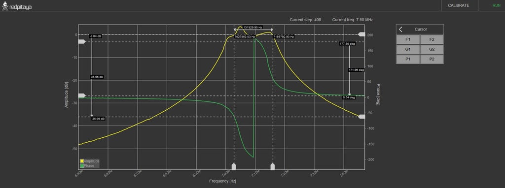
7MHz BPF (insertion lossはまあまあ正確な範囲にはいっているが、bandwidthが実際より、狭く測定されている。calibrationの取り方、stepをいくつにするかで、結果が変わってくる。3dB帯域やinsertion lossの正確な測定は、スペアナ/トラジェネや他の測定器のBode Plot(FRA) Sigelnt SDS1202X-E/SDS1104X-EとSDG2042X/SDG1082X/SDG1025)でのBode Plot測定が優秀なので、それに比べては現時点、見劣りするが、server接続で一応のBode Plot動作するのはいい事だと思う。やはり、calibrationで、start/stopの自由な設定ができること、また、stepを500から変更できるようになれば、もっと、精度が上がると考えられる。red pitayaには、reportして、改善されるように働きかけたいと思う。calibrationの幅を変えることができるようになれば、stepが多く設定できるため、もっと、精度が出る測定になると思う。
(1)calibrationは、いつも、100Hz-62MHz/500stepで行うので、目的周波数範囲のみで、calibrationが行う事ができるのが望ましい。改善を求める予定 (2)sma cableだけで、IN1/IN2のcable lengthまで同じにしていても、測定結果はhumpが現れる。もう少し、red pitayaにreport報告するまで、測定方法を検討したい。 ある程度の情報は得られるので、DUTにより、有効に使用できる場合もあるとは考えられる。 (3)calibration/measureに時間がかかる。たぶん、まだ、改善はしてくるのではないかと思います。
(テスト 2)

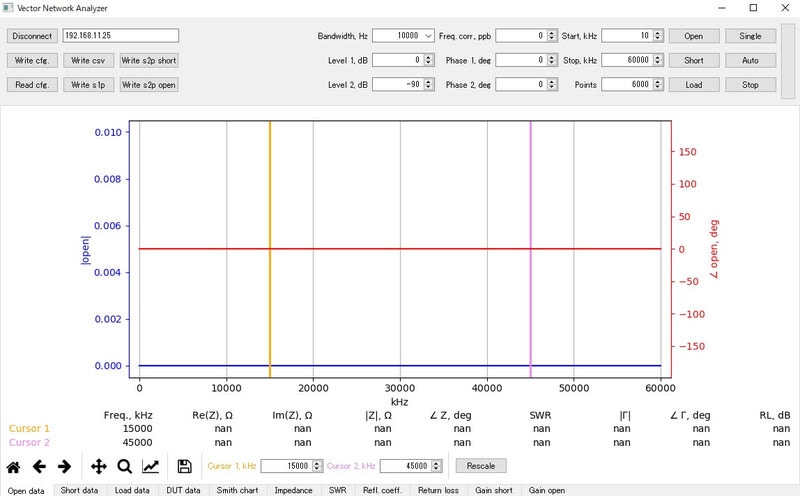
Linear calibrationを取って、そのまま、runすると

7MHz BPFの測定範囲は、見かけ上、フラットです。calibrationの各設定は、これ以外、今は変更ができません。測定(run)時、settingを6MHz-8MHz,step 1024とか、設定できるわけですが、やはり、plotting数がこの範囲で少ないと思います。stepは、400000とか設定できますが、もともと、calibration 500 stepでも時間がかかるため、400000だといつ終わるか、わからず、仮にうまくいっても、もともとのplottting数が少ないがために正確な測定は限界があるでしょう。
7MHz BPF測定用に接続、測定し、後からscaleを変更できるので、level.phase範囲を調整したのが以下です。

7MHz BPFのBode Plotが描出されています。35MHz-40MHzなどはきちんと、測定できないと判断できます。やはり、calibrationのstart/stop/stepを適宜、変更できるようにしてもらうのがいいかと思います。特に、start ferequencyが変更できるだけで、かなり違うと思います。400kHz範囲なら、500stepでも、かなり正確な測定ができるはずです。現在、vector network analyzerの事を聞いているので、それが終われば、状況説明して、calibrationの方法について、少なくとも、start frequencyを変更できるようにしてほしい旨、メールしたいと思います。
**************************************************
7MHz 受信(redpitaya HAMLab SDR Transceiver 最新 firmware and software)
https://www.youtube.com/watch?v=ANPu1KsL0Kk&feature=youtu.be
**************************************************
(I sent the message to Red Pitaya)
By the way,I'd like to talk with you about the Bode Analyzer.
I was measuring my 7MHz BPF
(center frequency 7.1MHz/Insertion loss -5.5dB/3dB bandwidth 90kHz for Software Defined Radio(Direct conversion type with pre-amplifier).
Its calibration is now only setting is
(1)100Hz-62MHz>>>I can't select the start and stop frequency
(2)steps(I think,it means plotting numbers and average numbers complex)>>>the steps are fixed the number as 500.
I measured like this(pic1)
When I calibarated as LIN(Linear),some frequency's calibration result is not good(But I don't care much,but I hope to become flat.lol)(pic2)
The result of measuring 7MHz BPF is like that(pic3)>>>Not precise !!
I think,it lacks of the plotting numbers at this range(7.0MHz--7.2MHz)
Also I think,your engineers don't expect to measure the narrow-band BPF(BW 100kHz and more like 3kHz crystal filter)
This 7MHz BPF is for the direct conversion type FPGA-Based SDR,when I use 30dB pre-amplifier to avoid the interference like images.
I am sorry,but it is comlicated a bit,I hope at first consider to alter the way of calibration.
Now only calibration is available/full band calibaration100Hz-62MHz(start 100Hz.stop 62MHz) and steps is 500 fixed.

So at first,I hope that the start frequency and stop frequwency can be slectable like start 6.8MHz and stop 7.2MHz.
And also I hope that the steps can be selectable freely.
If both are avaialble,I can get enough steps to get the precise measurement for this 7MHz BPF.
Technically it is possible,I know the example it is feasible to Bode Plot(FRA/Frequency Response Analysis)of Siglent SDS1204X-E and SDG2042X like this (pic4)
I also send you the link of this measurement on youtube.
I believe,Your HAMLab Bode Analyzer can do same precise measurement as Siglent's Bode Plots,if the way of calibration is selectable start /stop and steps.
もうすぐ、まず、Bode Analyzerのa release cadidateが用意できるとの事で、それができたら、また、テストします。
********************************************
Logic Analyzer PRO
最初出た頃は、PRO Versionのactivation codeがpre-orderで、無償でついてきました。現在は、購入時に、Logic Analyzer PROを79USDで選択するようになっています。
logic analyzerのタイプは、Saleae Logic Analyzerと同じで、データを125MSa/sなどで取り込んで、I2Cデコードなどを行います。Address/DATA表示が可能なので、例えば、確認したい、address 6EH/DATA 25H/DATA 36Hなど、頭だし表示が可能です。