I tried to repair the KX2 where the ATU malfunction recurred during the activation of Gongenyama.
↓現地で動作不良のATUをバイパスに設定したが、パワーが半分しか出て無かった。

↑I set the ATU to bypass at menu, but only half the power came out.
今回のATU不調は、10月の大松山移動で発覚したが、それ以降症状を見ようとしても、現象が出たりでなかったりで原因特定が出来ず、諦めてまた不具合が出るまで実戦で使っていたのだが、今回は戻って来てからも安定して症状が出てるようだ。
This ATU malfunction occurred when I moved to Omatsuyama in October, but after that, even if I tried to see the symptoms, I could not identify the cause because the phenomenon appeared or not. However, it seems that the symptoms have stabilized even after coming back this time.
パワーが半分しか出てないと言う事は、2合成しているPA部の片方がNGなんだな。
If only half the power is coming out, there is a high possibility that one side of the combined PA section is NG.
また、ATU不調でパワーが半分しか出てないと言うGroupes.ioの記事を10月の時に見つけていたが、それと似たような感じかもしれない。
Also, I found an article on Groupes.io in October saying that ATU was out of order and only half the power was coming out, but it may be similar to that.
この記事と、前回パワーが出なくなった時はドライバー不良だったので、今回も2系統あるうちのどちらかのドライバーがNGの確率が高い。
This article and the previous time when the power stopped coming out, the driver was defective, so this time there is a high probability that one of the two drivers will be NG.
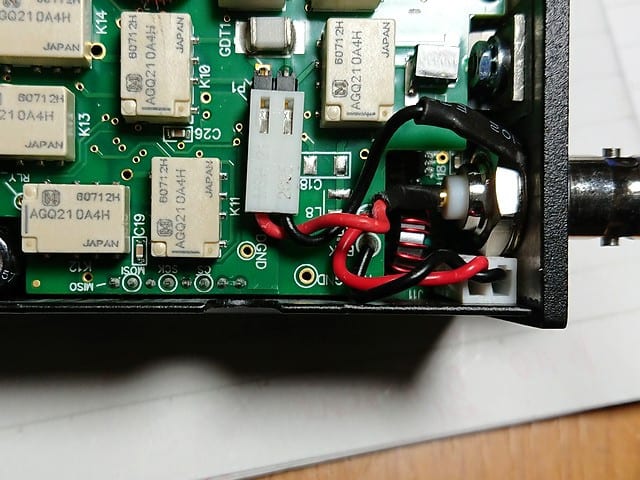
↓さっそく蓋を開けて中を確認する。赤枠のネジとコネクタを外してATU基板を外す。

↑Open the radio. Remove the screws and connectors framed in red to remove the ATU board.
↓赤枠の中が接続図の上側の系統のドライバーU20だ。

↑Inside the red frame is the driver U20 on the upper line of the schematic diagram.
反対側のU22は基板の裏なので、先ずはこちらが正常かどうかを調べる。
Other side of U22 is the back of the board, so first check this side.
↓ドライバーの入力と出力のレベルを確認する(写真は出力側)

↑Check the input and output levels of the driver (the photo is checked output)
前回は職場のスペアナを使ったが、毎度会社に持ってくのも面倒なので、TinySAとオシロプローブでレベル比較をする。
Last time I used a spectrum analyzer at work place, but since it is troublesome to bring it to the office every time, I compare levels with TinySA and oscilloscope probes.
↓入力側は-27dBm位を示す。

↑The input side shows about -27dBm.
↓出力側は、-34dBm位を示した。

↑The output side showed about -34dBm.
と言いう事で、ドライバーが増幅していないのは明らかだ。
So it's clear that the driver isn't amplifying.
ドライバー不良と確定する為には端子電圧等も測定した方が良いのだが、前回の事も有るので、ほぼ間違いないだろうと、それ以上の調査は打ち切った。
In order to conclude that the driver is defective, it would be better to measure the terminal voltage, etc., but since there was also the previous incident, I decided that there was almost no mistake, and further investigation was discontinued.
ちなみ、TinySAはデフォルトだとRefレベルがオートになっているので、勝手にレベルの目盛り位置が変わって非常にレベル比較しにくかった。メニューから、RefレベルとATTを固定してから測定した。
By the way, TinySA's Ref level is set to auto level select mode by default, so it was very difficult to compare levels because the position of the level scale changed arbitrarily. I fixed the Ref level and ATT from the menu and then measured.
あまりRefレベルが勝手に変わるスペアナって職場では見た事がないのでちょっと戸惑ってしまった。
I've never seen a spectrum analyzer that changes the Ref level on its own at work place, so I was a little confused.
ドライバーICは前回の修理の時に余分に買って有ったので早速交換する。
I bought an extra driver IC at the last repair, so I will replace it immediately.
↓まずは半田を沢山盛って、U20(SGA7489)を取り外す。

↑First, put a lot of solder and remove U20 (SGA7489).
↓取り外したU20(SGA7489)

↑Removed U20 (SGA7489)
↓手前のpinだけ予備半田をして置き、新しいSGA7489を載せて仮半田する。

↑Preliminarily solder only the near side pin, place a new SGA7489, and temporarily solder it.
↓その後残りの端子も合わせて放熱を兼ねて沢山半田を盛ってのはんだ付け。

↑Solder the remaining terminals together with a lot of solder as heat think.
これで、修理完了。元通りに組み上げる。
The repair is now complete. Reassemble as before.
↓ディスプレイ上とパワー計で確認すると無事に10W出る様になった。

↑Checked it on the display and with the power meter, it came to output 10W.
無事にATUも正常に動くようになった。
ATU is now working normally.
これで、いつ壊れるか心配しながら運用しなくても済みそうだ。
With this, I don't have to worry about when it will break.
とここ迄ブログを書いてから、新品ドライバー取り付け後の写真がヤニヤニなのに気が付いて、一旦ATUボード迄ばらして、ドライバーICをシンナーで綺麗にした後の写真が上の「沢山半田を盛って」の写真である。
After writing this blog, I noticed that the pictures after soldering the new driver were dirty. I took apart the ATU board again and cleaned the driver IC with thinner. That is the picture after the IC exchange above.
その後組み上げて、元通りにしてしまっておいたのだが、翌日もう一度電源を入れたら、初期診断でERR表示が出た。
I reassembled it and put it away for a while, but when I turned it on again the next day, ERR was displayed in the initial diagnosis.
↓電源投入直後のERR表示「d=001 ERR ATC」が出る。

↑The ERR display " d=001 ERR ATC" appears after the power on.
あれあれ、なんで?
Why?
メニューからATUの設定を確認するがちゃんとATU MDはAUTOになってる。
Check the ATU setting from the menu, but ATU MD is set to AUTO.
取説を調べると「ERR ATC」はATUが付いてない時に出るらしい。(メニューでATU MDがnot inst以外の時)
According to the manual, "ERR ATC" appears when ATU is not attached. (When ATU MD is other than not inst in the menu)
8ピンコネクタ正しく刺さってる?ATUを組みなおしてみろ!と書かれている。
Is the 8-pin connector inserted correctly? Reassemble ATU! it is written like this.
一旦外してATUを組みなおすが、状況は変わらない。
I removed it once and reassembled the ATU, but the situation did not change.
コネクタは刺さっていると思うが、基板の下なので直接は見えない。
I think the connector is sticking, but it's under the board so I can't see it directly.
でも、基板を少し上下に動かすと、刺さってる様な摺動抵抗を感じるし、持ち上げすぎるとそれが外れて無くなるし、押し込みすぎると基板に当たるのか突き当たるし、、、、
However, if you move the board up and down a little bit, you will feel a sliding resistance as if it is sticking in. If you lift it too much, it will come off and disappear.
3回位抜き差ししてみても一向にERRは消えない。
ERR does not disappear at all even if I try to insert and remove it about 3 times.
参ったなぁ、、、と考えてる時に、そういえばATUボードを機械的に外して電気的接続したままTRXボードの様子が見れるように、8ピンの延長ケーブルとRFの延長ケーブルを作ったのを思い出した。
When I was thinking that I was overwhelmed, I remembered. I made an 8-pin extension cable and RF extension cables.
↓自作した延長ケーブル類

↑Self-made extension cables
↓さっそくこれを付けてみる。

↑I'm going to use these on now.
↓これだとうまく起動する。

↑This works fine.
う~ん、なんで??Hmm, why? ?
これも3回位、延長したり、直付けにしたりを試したが、延長した時は必ずOKで、直付けすると必ずERR。
I also tried to extend it and attach it directly about 3 times.
う~ん、判らん??
Hmm, I don't know? ?
試しにRF延長ケーブルや、縦に付いてるBPFの小基盤を外しても、8ピン延長ケーブルがつながっていればERRは出ない。
Even if you remove the RF extension cable and the vertical BPF small board as a test, ERR will not appear if the 8-pin extension cable is connected.
と言う事はやっぱり8ピンがつながってないのか??
Does that mean the 8 pin is not connected? ?
訳が判らなくなって、下のTRX基盤を良く眺めていると、ATU基板のコネクタと比べて、コネクタ位置が基板の端から少し離れているのに気が付いた。
I didn't understand why, and when I looked closely at the TRX board below, I noticed that the connector position was a little far from the edge of the board compared to the connector on the ATU board.
↓基盤のエッジから少し離れて黒い8ピンコネクタが有る。

↑There is a black 8-pin connector a little away from the edge of the board.
ATU基板上の8ピンコネクタは基板の一番端に付いてる。
The 8-pin connector on the ATU board is attached to the very edge of the board.
もしかしてコネクタに刺したつもりが、コネクタの外側(筐体側)にピンがずれて下のコネクタの横を擦ってるだけか?
Did you intend to insert it into the connector, but the pin was shifted to the outside of the connector (the side of the chases) and just rubbed the side of the lower connector?
今度は組み立て時に、意識して少し内側にコネクタを差し込むつもりでATU基板を取り付けた。
This time, when assembling, I consciously installed the ATU board with the intention of inserting the connector a little inside.
起動するとERR表示は出なくなった。やった、これか!!
When I power on it, the ERR display disappeared. Yay, this is it! !
↓ATU基板を良く見ると筐体から少し離れているのが判る。

↑If you look closely at the ATU board, you can see that it is a little far from the housing.
そうか、正しく挿してるつもりが、外側に外れてたのね。
I thought I was inserting it correctly, but it came off the outside.
と言う事で、起動時のERRも消えて、無事にATUも動くようになった。
The ERR at startup disappeared, and ATU also started to work correctly.
修理後の、KX2のATU動作の様子↓
KX2's ATU operation after repair↑
今回壊れた片側だけドライバーを交換したが、反対側も同様にストレスは掛かっているよなぁ、、、まあ、又壊れた時に直せばいいか。メーカー送りだと大変だけど自分で治すなら簡単だしね。
I replaced the IC only on one side that was broken this time, but the other side is similarly stressed... Well, should I fix it when it breaks again.
Sending it to the manufacturer takes time, but it's easy if I fix it myself.
しかし、KX2を投入したのが2020年8月、前回のトラブルが2021年3月、今回が2022年10月と1回目8か月、2回目1年半で、同じ所が壊れている。いくら中古で買った物だと言ってもちょっと壊れすぎな気がする。
However, I started using the KX2 in August 2020, the last trouble was in March 2021, this time in October 2022, the first time eight months, the second time a year and a half, and the same place is broken. Even though I bought it second-hand, I feel like it would break easily.
でも、KX2が壊れた話はSOTA関連の周りの人では1人しか聞いた事がない。
But I haven't heard much from SOTA people about the KX2 being broken.
これは私の使い方が、LWをATUで強引に使っている事に起因しているのかも。
This may be due to my use of forceful use of plain LW in ATU.
TUNE中はパワーが自動的に下がるが、それでも反射波によるファイナルの入出力インピーダンス変動が大きく、ファイナルの入力インピの乱れがドライバーに対するVSWRを悪化させ、その反射電力で、耐性的に弱いドライバー側が先に逝ってしまうと言うストーリーだろうか?
The power is automatically reduced during TUNE, but the final input/output impedance fluctuation due to the reflected wave is still large. Is it a story that the disturbance of the input impedance of the final worsens the VSWR to the driver, and the reflected power causes the driver side, which is weak in resistance, to die first?
他の人は、DP、VCH、EFにしろ、ある程度VSWRは合わせてるもんなぁ、、、
Other SOTA peaples, whether it's DP, VCH, or EF, they matched the VSWR...
KX2はかなり広範囲にATUが押さえ込んでくれるから、それに頼りすぎてVSWRで横着すると、壊れやすくなると言った所だろうか?
The KX2's ATU matches a fairly wide range of impedances, so if you rely too much on it, it might break easily.
今後はATU無しでもそこそこVSWRが収まる様にアンテナを用意しないとなぁ、、、
From now on, even without ATU, I have to prepare a tuned antenna...
2022.12.18 (12/22 UP)
エレクラフト KX2 修理 2021/3/18
KX2 修理 ATU動作不良⇒ドライバー交換 2022/12/18
KX2再修理;ATU動作不良、HI CUR 表示、POW出ず 2022/12/28


