


With the improvement of the technology level of machine tool manufacturing industry, CNC machine tools have been put into various parts processing and automated production lines, which will be an indispensable connection device for major smart factories in the future.
There are two major types of CNC machine tools: metal cutting equipment and sheet metal equipment. According to their control principles, functions, and components, they are classified from different perspectives, and are mainly divided into the following categories:
First, in the processing of parts of the hole system, point-controlled CNC machine tools.
The point control NC machine tools mainly include NC drilling machines, NC boring machines, NC punches, and coordinate measuring machines. The printed circuit board drilling machine is the simplest point control NC machine tool. The point-controlled NC machine tool is used to process the hole system in the plane. By controlling the two coordinate axes in the machining plane, the tool and the workpiece are moved relative to each other. The machining method is to quickly move from one coordinate position to the next coordinate position, and then control the third coordinate axis for cutting.
This type of machine tool requires high positioning accuracy of the coordinate position. In order to improve production efficiency, the machine tool uses the set maximum feed speed for positioning movement, and advances or grades continuously near the positioning point in order to approach the end point at low speed, thereby reducing Inertial overshoot of moving parts and the resulting positioning errors. During the positioning and moving process, the CNC machine tool does not cut and does not have any requirements on the motion trajectory.
Second, in cutting processing, the most widely used linear control CNC machine tools.
The linear control CNC machine tool can control the appropriate feed speed of the tool or table, and perform linear movement and cutting in a direction parallel to the coordinate axis. The feed speed can be adjusted within a certain range according to the cutting conditions. Linear control CNC lathes with only two coordinate axes are used for machining step axes. Three-axis linear control CNC milling machine can be used for plane milling. Modern combined machine tools use a numerically controlled feed servo system. The drive power head carries multiple axis boxes to feed in the axial direction for cutting. It can also be regarded as a linearly controlled numerically controlled machine tool.
Third, CNC machine tools for complex parts with curve and contour control.
Contour CNC machine tools are divided into planar contour machining NC machine tools and spatial CNC machine tools. The CNC machine tools for plane contour processing include CNC lathes for turning curved parts and CNC milling machines for milling curved contours. They are distinguished according to the contour shapes of the processed parts. No matter what kind of line segment the component contour is composed of, usually a small straight line is used to approximate the contour of the curve during processing.
Using the calculated two displacement components to instruct the two coordinate axes to move simultaneously, this control method is called two-coordinate linkage control. When turning curved parts with a circular cutting edge turning tool with radius R, interpolation calculation and tool radius compensation calculation are also performed. When machining with a cutting edge turning tool with radius R=0, direct calculation can be performed according to the contour of the workpiece, and the problem of tool center offset does not need to be considered. Therefore, the calculation of tool radius compensation is not necessary, only interpolation calculation is performed. CNC machine tools capable of two-coordinate linkage control can also generally perform point and linear control.
There are several processing methods according to the shape of the processed parts:
① On a machine tool with three-coordinate control and two-coordinate linkage, use the "line cutting method" for processing. This method is also called two-axis semi-control, that is, any two of the X, Y, and Z axes perform interpolation motion, the third axis performs periodic feed motion, and the tool uses a ball-end milling cutter.
②Three coordinate linkage processing. The track bus SS'of the ball-return device of the inner-circulating ball nut is a spatial curve, which can be approximated by a spatial straight line, and can be processed on a three-coordinate linkage bed with a linear linear interpolation function. However, the programming calculation is more complicated, and the processing program can be prepared by an automatic programming system.
③ Four coordinate linkage processing. The processed surface of the aircraft beam is a straight twisted surface. If it is processed by a three-coordinate linkage machine tool and a ball-end milling cutter, not only the productivity is low, but the surface roughness of the part is also very poor. The peripheral milling method of cylindrical milling cutter is used to process on a four-coordinate machine. In addition to the linkage of three moving coordinates, in order to ensure that the tool and the workpiece profile are always fitted over the entire length, the tool should also perform a swing linkage around the spindle. This swing linkage results in an additional compensation movement for the linear movement coordinates. The additional movement amount is related to the position of the pendulum. It must also be calculated during programming.
④ Five-coordinate linkage processing. Almost all space contours can be machined with a ball-end milling cutter in the "line-cutting" method. For some large curved contours, the size of the part and the radius of curvature of the curved surface are relatively large. Switching to a face milling cutter can improve productivity and reduce the residual amount of processing.
During machining, the coordinates of the cutting point and the direction angle θ of the normal line are constantly changing, so the coordinates of the tool position point and the direction angle of the tool axis must be changed accordingly. The current CNC machine tools calculate the coordinates and orientation angles (that is, tool position data) of the tool position points corresponding to each cutting point according to the mathematical model of the contour of the part surface when programming the machining program, and input them to the CNC system through the program.
The coordinate position of the tool position point is realized by three linear feed coordinate axes, and the directional angle of the tool axis can be synthesized by any two rotation angles of rotation around the coordinate axis. Therefore, when machining a surface curved surface with a face milling cutter, it is necessary to control five coordinate axes (three linear coordinate axes and two circumferential feed coordinate axes) for linkage. The five-axis linkage CNC machine tool is the most complete and most complex type of CNC machine tool. The programming of five-axis linkage machining is also the most complicated. It should be prepared by using an automatic programming system.
The above classification is mainly based on the machining functions of CNC machine tools. If classified from the perspective of the number of control axes and the number of linkage axes, CNC machine tools can be divided into two-axis linkage CNC machine tools, three-axis control two-axis linkage CNC machine tools, four-axis linkage CNC bed and five-axis linkage CNC machine tools.
最新の画像[もっと見る]
-
 Việc bảo quản tem nhãn decal cần phải chú ý những gì?
4年前
Việc bảo quản tem nhãn decal cần phải chú ý những gì?
4年前
-
 Boat Winch
6年前
Boat Winch
6年前
-
 How to keep your Police Badge well?
7年前
How to keep your Police Badge well?
7年前
-
 SINGLE-PHASE KEYPAD PREPAID ENERGY METER DDSY1398
7年前
SINGLE-PHASE KEYPAD PREPAID ENERGY METER DDSY1398
7年前
-
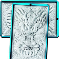
 JIAN-Acrylic Medal with Exquisite Metal Frame
7年前
JIAN-Acrylic Medal with Exquisite Metal Frame
7年前
-
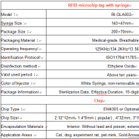 Rayidea™ Implanted RFID Animal Tag (P/N: RI-GLA002)
8年前
Rayidea™ Implanted RFID Animal Tag (P/N: RI-GLA002)
8年前
-
 Rayidea™ Implanted RFID Animal Tag (P/N: RI-GLA002)
8年前
Rayidea™ Implanted RFID Animal Tag (P/N: RI-GLA002)
8年前
-
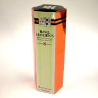 6 top women’s description gift boxes
8年前
6 top women’s description gift boxes
8年前
-
"Internet +" to create green cardboard boxes
8年前
-
 Application for 3D laser engraving
8年前
Application for 3D laser engraving
8年前
※コメント投稿者のブログIDはブログ作成者のみに通知されます