ルネサス製のRX210マイコンのチップ内蔵の温度計からデータを取り出すサンプルプログラムです。
- #include "iodefine.h"
- #include <stdio.h>
- #include <machine.h>
- #include "rs232c.h"
-
- /*
- * ADコンバータと温度センサーの初期化
- */
- void ad_init(void)
- {
- SYSTEM.PRCR.WORD = 0xA502; /* protect off */
- MSTP(S12AD) = 0; /* ADコンバータ */
- MSTP(TEMPS) = 0; /* 温度センサー */
- SYSTEM.PRCR.WORD = 0xA500; /* protect on */
- //MPC.PWPR.BIT.B0WI = 0; /* enable to write PFSWE bit */
- //MPC.PWPR.BIT.PFSWE = 1; /* enable to write PFS register */
- //MPC.P40PFS.BIT.ASEL = 1; /* AN000 */
- //MPC.P41PFS.BIT.ASEL = 1; /* AN001 */
- //MPC.PWPR.BIT.PFSWE = 0; /* disable to write PFS register */
- //MPC.PWPR.BIT.B0WI = 1; /* disable to write PFSWE bit */
- S12AD.ADEXICR.BIT.TSS = 1; /* 温度センサー選択 */
- S12AD.ADCSR.BIT.ADCS = 0; /* シングルスキャンモード */
- S12AD.ADSSTRT = 100; /* アナログ入力サンプリング時間 */
- S12AD.ADSTRGR.BIT.TRSA = 0x0A; /* AD開始トリガー設定 温度センサからのトリガ */
- S12AD.ADCSR.BIT.TRGE = 1; /* 温度センサーからのトリガーを有効 */
- S12AD.ADCSR.BIT.EXTRG = 0;
- TEMPS.TSCR.BIT.PGAGAIN = 0x01; /* 電源電圧 3.3V */
- }
- /*
- * 温度の測定
- */
- unsigned int get_temp(void)
- {
- volatile int i;
- unsigned int temp;
- TEMPS.TSCR.BIT.TSEN = 1; /* 温度センサー起動 */
- for(i=0;i<1000;i++); /* 安定するまで待つ */
- TEMPS.TSCR.BIT.PGAEN = 1; /* PGA動作 A/D変換スタート */
- while(TEMPS.TSCR.BIT.PGAEN == 1); /* A/D変換終了まで待つ */
- temp = S12AD.ADTSDR; /* 結果の読み出し */
- TEMPS.TSCR.BIT.TSEN = 0; /* 温度センサー停止 */
- return temp;
- }
- /*
- * メイン関数
- */
- void main(void)
- {
- char buf[256];
- unsigned int t;
- volatile int i;
- change_oscillation_PLL(); //クロックソースPLL 50MHz
- SCI_Init ();
- ad_init();
- setpsw_i(); // 割込み許可 clrpsw_i()割込み禁止
- printString("chip thermometer test program\n");
- printString("use SCI0\n");
- while(1) {
- t = get_temp();
- sprintf(buf,"temperature %x\n",t);
- printString(buf);
- for(i=0;i<800000;i++);
- }
- }
ルネサス製のRX210マイコンのSCI0を使用したシリアル通信プログラムのサンプルです。
リングバッファと割り込みを使用しています。
change_oscillation_PLL()関数
リングバッファと割り込みを使用しています。
- /*
- * interrupt_handlers.c のSCI0関連の割り込みをコメントアウトすること
- * // SCI0 ERI0
- * //void Excep_SCI0_ERI0(void){ }
- *
- * // SCI0 RXI0
- * //void Excep_SCI0_RXI0(void){ }
- *
- * // SCI0 TXI0
- * //void Excep_SCI0_TXI0(void){ }
- *
- * // SCI0 TEI0
- * //void Excep_SCI0_TEI0(void){ }
- *
- */
- #include "iodefine.h"
- #include <stdio.h>
- #include <machine.h>
- #include "vect.h"
- #define PCLK 25 //PクロックMHz
- #define TX_ACTIVE 1 //送信動作中
- #define TX_INACTIVE 0 //送信停止中
- #define TX_RING_BUFF_SIZE 32 //リングバッファのサイズ
- #define RX_RING_BUFF_SIZE 32 //リングバッファのサイズ
- //リングバッファ
- unsigned char rx_buff[RX_RING_BUFF_SIZE]; //受信用
- unsigned char tx_buff[TX_RING_BUFF_SIZE]; //送信用
- //データポインタ
- volatile int ptr_rx_top,ptr_rx_bottom;
- volatile int ptr_tx_top,ptr_tx_bottom;
- //送信フラグ データ送信中かどうか
- volatile int tx_flag = TX_INACTIVE;
- /*
- * SCI0初期化
- * 57600bps: 8bit: stop bit 1: Parity none
- * PCLK 25MHz
- */
- void SCI_Init (void)
- {
- /* ---- SCI interrupt request is disabled ---- */
- IR(SCI0,ERI0) = 0;
- IR(SCI0,RXI0) = 0;
- IR(SCI0,TXI0) = 0;
- IR(SCI0,TEI0) = 0;
- /* ---- Initialization of SCI ---- */
- /* PRCR - Protect Register
- b15:b8 PRKEY - PRC Key Code - A5h (The write value should be A5h to permission writing PRCi bit)
- b7:b4 Reserved - The write value should be 0.
- b1 PRC1 - Protect Bit 1 - Write enabled */
- SYSTEM.PRCR.WORD = 0xA502;
- /* The module stop state of SCIn is canceled */
- MSTP(SCI0) = 0;
- /* Enable write protection */
- SYSTEM.PRCR.WORD = 0xA500;
- /* SCR - Serial Control Register
- b7 TIE - Transmit Interrupt Enable - A TXI interrupt request is disabled
- b6 RIE - Receive Interrupt Enable - RXI and ERI interrupt requests are disabled
- b5 TE - Transmit Enable - Serial transmission is disabled
- b4 RE - Receive Enable - Serial reception is disabled
- b2 TEIE - Transmit End Interrupt Enable - A TEI interrupt request is disabled */
- SCI0.SCR.BYTE = 0x00;
- while (0x00 != (SCI0.SCR.BYTE & 0xF0))
- {
- /* Confirm that bit is actually 0 */
- }
- /* ---- Set the I/O port functions ---- */
- /* Set port output data - High level */
- PORT2.PODR.BIT.B0 = 1;
- /* Set port direction - TXDn is output port, RXDn is input port */
- PORT2.PDR.BIT.B0 = 1;
- PORT2.PDR.BIT.B1 = 0;
- /* Set port mode - Use pin as general I/O port */
- PORT2.PMR.BIT.B1 = 0;
- PORT2.PMR.BIT.B0 = 0;
- /* PWPR - Write-Protect Register
- b7 B0WI - PFSWE Bit Write Disable - Writing to the PFSWE bit is enabled
- b6 PFSWE - PFS Register Write Enable - Writing to the PFS register is enabled
- b5:b0 Reserved - These bits are read as 0. The write value should be 0. */
- MPC.PWPR.BIT.B0WI = 0;
- MPC.PWPR.BIT.PFSWE = 1;
- /* PFS - Pin Function Control Register
- b3:b0 PSEL - Pin Function Select - RXDn, TXDn */
- MPC.P20PFS.BYTE = 0x0A;
- MPC.P21PFS.BYTE = 0x0A;
- /* Enable write protection */
- MPC.PWPR.BIT.PFSWE = 0;
- MPC.PWPR.BIT.B0WI = 1;
- /* Use pin as I/O port for peripheral functions */
- PORT2.PMR.BIT.B1 = 1;
- PORT2.PMR.BIT.B0 = 1;
- /* ---- Initialization of SCI ---- */
- /* Select an On-chip baud rate generator to the clock source */
- SCI0.SCR.BIT.CKE = 0;
- /* SMR - Serial Mode Register
- b7 CM - Communications Mode - Asynchronous mode
- b6 CHR - Character Length - Selects 8 bits as the data length
- b5 PE - Parity Enable - When transmitting : Parity bit addition is not performed
- When receiving : Parity bit checking is not performed
- b3 STOP - Stop Bit Length - 1 stop bits
- b2 MP - Multi-Processor Mode - Multi-processor communications function is disabled
- b1:b0 CKS - Clock Select - PCLK clock (n = 0) */
- SCI0.SMR.BYTE = 0x00;
- /* SCMR - Smart Card Mode Register
- b6:b4 Reserved - The write value should be 1.
- b3 SDIR - Transmitted/Received Data Transfer Direction - Transfer with LSB-first
- b2 SINV - Transmitted/Received Data Invert - TDR contents are transmitted as they are.
- Receive data is stored as it is in RDR.
- b1 Reserved - The write value should be 1.
- b0 SMIF - Smart Card Interface Mode Select - Serial communications interface mode */
- SCI0.SCMR.BYTE = 0xF2;
- /* SEMR - Serial Extended Mode Register
- b7:b6 Reserved - The write value should be 0.
- b5 NFEN - Digital Noise Filter Function Enable - Noise cancellation function
- for the RXDn input signal is disabled.
- b4 ABCS - Asynchronous Mode Base Clock Select - Selects 16 base clock cycles for 1-bit period
- b3:b1 Reserved - The write value should be 0. */
- SCI0.SEMR.BYTE = 0x00;
- /* BRR - Bit Rate Register
- Bit Rate: (25MHz/(64*2^(-1)*57600bps))-1=12.56 */
- SCI0.BRR = 13; /* 57600bps */
- //SCI0.BRR = 40; /* 19200bps */
- /* ---- Initialization of SCI interrupt ---- */
- /* SCI interrupt priority level is 1 */
- IPR(SCI0, ) = 1;
- /* Interrupt request is cleared (Edge interrupt) */
- IR(SCI0,RXI0) = 0;
- IR(SCI0,TXI0) = 0;
- /* 割り込みの許可 */
- IEN(SCI0, RXI0) = 1;
- IEN(SCI0, ERI0) = 1;
- IEN(SCI0, TXI0) = 1;
- IEN(SCI0, TEI0) = 1;
- /* リングバッファの初期化 */
- ptr_rx_top = ptr_rx_bottom = 0;
- ptr_tx_top = ptr_tx_bottom = 0;
- /* 送受信許可 */
- SCI0.SCR.BIT.RIE = 1; //受信割込み
- SCI0.SCR.BIT.TIE = 1; //送信割込み
- SCI0.SCR.BIT.RE = 1; //受信動作開始
- SCI0.SCR.BIT.TE = 0;
- }
- /*
- * 受信エラー割り込み
- */
- /* SSR - Serial Status Register
- b7:b6 Reserved - The read value is undefined. The write value should be 1.
- b5 ORER - Overrun Error Flag - An overrun error has occurred
- b4 FER - Framing Error Flag - A framing error has occurred
- b3 PER - Parity Error Flag - A parity error has occurred */
- #define SSR_ERROR_FLAGS (0x38)
- void Excep_SCI0_ERI0(void)
- {
- volatile char c;
- c = SCI0.RDR; //ダミーリード
- SCI0.SSR.BYTE = (SCI0.SSR.BYTE & ~SSR_ERROR_FLAGS) | 0xC0; //エラーフラグクリア
- }
- /*
- * 受信バッファフル割込み
- */
- void Excep_SCI0_RXI0(void)
- {
- /* Read data */
- rx_buff[ptr_rx_top] = SCI0.RDR;
- ptr_rx_top++;
- ptr_rx_top = ptr_rx_top % RX_RING_BUFF_SIZE;
- }
- /*
- * 送信バッファエンプティ割込み
- */
- void Excep_SCI0_TXI0(void)
- {
- if( ptr_tx_bottom == ptr_tx_top ) { //送信するデータがない
- SCI0.SCR.BIT.TEIE = 1; //送信終了割り込みの発生を待つ
- } else {
- /* Write the character out */
- SCI0.TDR = tx_buff[ptr_tx_bottom];
- ptr_tx_bottom++;
- ptr_tx_bottom = ptr_tx_bottom % TX_RING_BUFF_SIZE;
- }
- }
- /*
- * 送信終了割り込み
- */
- void Excep_SCI0_TEI0 (void)
- {
- SCI0.SCR.BIT.TE = 0; //送信停止
- IR(SCI0,TXI0) = 0; //割り込みフラグクリア
- SCI0.SCR.BIT.TEIE = 0; //送信完了割込み停止
- tx_flag = TX_INACTIVE; //送信回路フラグを停止に
- }
- /*
- * データの送信
- */
- void SCI_put(unsigned char output_char)
- {
- int tmp;
- tmp = ptr_tx_top + 1;
- tmp = tmp % TX_RING_BUFF_SIZE;
- while(tmp == ptr_tx_bottom) ; //バッファに空きができるまで待つ
- tx_buff[ptr_tx_top] = output_char;
- ptr_tx_top++;
- ptr_tx_top = ptr_tx_top % TX_RING_BUFF_SIZE;
- if(tx_flag == TX_INACTIVE) {
- tx_flag = TX_ACTIVE; //送信回路フラグを動作に
- SCI0.SCR.BIT.TE = 1; //送信割込み許可
- SCI0.SCR.BIT.TEIE = 0; //送信完了割込み停止
- }
- }
- void charput(unsigned char c)
- {
- //while(IR(SCI0,TXI0)==0) ;
- if(c=='\r' || c=='\n') {
- SCI_put('\r');
- SCI_put('\n');
- } else {
- SCI_put(c);
- }
- }
- /* データの受信 バッファに受信したデータがなければ受信するまで待つ */
- unsigned int SCI_get(void)
- {
- unsigned char c;
- while(ptr_rx_bottom == ptr_rx_top); //データを受信するまで待つ
- c = rx_buff[ptr_rx_bottom];
- ptr_rx_bottom++;
- ptr_rx_bottom = ptr_rx_bottom % RX_RING_BUFF_SIZE;
- return c;
- }
- unsigned int charget(void)
- {
- return SCI_get();
- }
- /*
- * 文字列の出力
- */
- void printString(char *s)
- {
- while( *s != 0 ) {
- charput(*s);
- s++;
- }
- }
- /*
- * printf関数で使用
- */
- int _write(int file,char *ptr,int len)
- {
- int i;
- for(i=0;i<len;i++) {
- charput(ptr[i]);
- }
- return len;
- }
- /*
- * scanf関数で使用
- */
- int _read (int file, char *ptr, int len)
- {
- *ptr = charget();
- return 1;
- }
- void main(void)
- {
- char buf;
- change_oscillation_PLL(); //クロックソースPLL
- SCI_Init ();
- setpsw_i(); // 割込み許可 clrpsw_i()割込み禁止
- printString("RS232C test program\n");
- printString("use SCI0123\n");
- while(1) {
- buf = charget();
- _write(0,&buf,1);
- }
- }
change_oscillation_PLL()関数
/* * 動作クロックをPLLで50MHzに設定 */ void change_oscillation_PLL(void) { unsigned int i; /* ---- Enable write protection ---- */ /* PRCR - Protect Register b15:b8 PRKEY - PRC Key Code - A5h (The write value should be A5h to permission writing PRCi bit) b7:b4 Reserved - The write value should be 0. b3 PRC3 - Protect Bit 3 - Write disabled b2 PRC2 - Protect Bit 2 - Write enabled b1 PRC1 - Protect Bit 1 - Write enabled b0 PRC0 - Protect Bit 0 - Write enabled */ SYSTEM.PRCR.WORD = 0xA507; /* ---- Set the VRCR register ---- */ SYSTEM.VRCR = 0x00; /* ---- Set the main clock oscillator drive capability ---- */ /* MOFCR - Main Clock Oscillator Forced Oscillation Control Register b7 Reserved - The write value should be 0. b6 MOSEL - Main Clock Oscillator Switch - Resonator b5:b4 MODRV2 - Main Clock Oscillator Drive Capability Switch 2 - 16 MHz to 20 MHz b3:b1 MODRV - Main Clock Oscillator Drive Capability Switch - 16 MHz to 20 MHz non-lead type ceramic resonator b0 Reserved - The write value should be 0. */ SYSTEM.MOFCR.BYTE = (0x30); /* Drive capability : 20 MHz crystal resonator */ /* ---- Set wait time until the main clock oscillator stabilizes ---- */ /* MOSCWTCR - Main Clock Oscillator Wait Control Register b7:b5 Reserved - The write value should be 0. b4:b0 MSTS - Main Clock Oscillator Waiting Time - Wait time is 131072 cycles (approx. 6.55 ms). */ SYSTEM.MOSCWTCR.BYTE = (0x0D); /* Wait control register : 131072 cycles (approx. 6.55 ms) */ /* ---- Operate the main clock oscillator ---- */ /* MOSCCR - Main Clock Oscillator Control Register b7:b1 Reserved - The write value should be 0. b0 MOSTP - Main Clock Oscillator Stop - Main clock oscillator is operating. */ SYSTEM.MOSCCR.BYTE = 0x00; while (0x00 != SYSTEM.MOSCCR.BYTE) { /* Confirm that the written value can be read correctly. */ } /* ---- Wait processing for the clock oscillation stabilization ---- */ for(i=0;i<100;i++) nop(); /* ---- Set the PLL division ratio and multiplication factor ---- */ /* PLLCR - PLL Control Register b15:b13 Reserved - The write value should be 0. b12:b8 STC - Frequency Multiplication Factor Select - Frequency multiplication factor is multiply-by-10. b7:b2 Reserved - The write value should be 0. b1:b0 PLIDIV - PLL Input Frequency Division Ratio Select - PLL input division ratio is divide-by-2. */ SYSTEM.PLLCR.WORD = (0x0901); /* Division ratio and multiplication factor : divide-by-2, multiply-by-10 */ /* ---- Set wait time until the PLL clock oscillator stabilizes ---- */ /* PLLWTCR - PLL Wait Control Register b7:b5 Reserved - The write value should be 0. b4:b0 PSTS - PLL Waiting Time - Wait time is 65536 cycles (approx. 655.36 us). */ SYSTEM.PLLWTCR.BYTE = (0x09); /* Wait control register : 65536 cycles (approx. 655.36 us) */ /* ---- Operate the PLL clock oscillator ---- */ /* PLLCR2 - PLL Control Register 2 b7:b1 Reserved - The write value should be 0. b0 PLLEN - PLL Stop Control - PLL is operating. */ SYSTEM.PLLCR2.BYTE = 0x00; /* ---- Wait processing for the clock oscillation stabilization ---- */ for(i=0;i<100;i++) nop(); /* ---- Set the operating power control mode ---- */ /* OPCCR - Operating Power Control Register b7:b5 Reserved - The write value should be 0. b4 OPCMTSF - Operating Power Control Mode Transition Status Flag b3 Reserved - The write value should be 0. b2:b0 OPCM - Operating Power Control Mode Select - High-speed operating mode */ SYSTEM.OPCCR.BYTE = (0x00); /* High-speed operating mode */ while (0 != SYSTEM.OPCCR.BIT.OPCMTSF) { /* Confirm that the operation power control mode transition completed. */ } /* ---- Set the internal clock division ratio ---- */ /* SCKCR - System Clock Control Register b31:b28 FCK - FlashIF Clock(FCLK) Select - divide-by-4 b27:b24 ICK - System Clock (ICLK) Select - divide-by-2 b23 PSTOP1 - BCLK Pin Output Control - disabled. (Fixed high) b22:b20 Reserved - The write value should be 0. b19:b16 BCK - External Bus Clock (BCLK) Select - divide-by-4 b15:b12 Reserved - The write value should be 0001b. b10:b8 PCLKB - Peripheral Module Clock B(PCLKB) Select - divide-by-4 b7:b4 Reserved - The write value should be 0001b. b3:b0 PCLKD - Peripheral Module Clock D(PCLKD) Select - divide-by-2 */ SYSTEM.SCKCR.LONG = 0x21821211; /* ICLK,PCLKD: divide-by-2 PCLKB,BCLK,FCLK: divide-by-4 */ while (0x21821211 != SYSTEM.SCKCR.LONG) { /* Confirm that the written value can be read correctly. */ } /* ---- Set the BCLK pin output ---- */ /* BCKCR - External Bus Clock Control Register b7:b1 Reserved - The write value should be 0. b0 BCLKDIV - BCLK Pin Output Select - divide-by-2 */ SYSTEM.BCKCR.BYTE = 0x01; while (0x01 != SYSTEM.BCKCR.BYTE) { /* Confirm that the written value can be read correctly. */ } /* ---- Set the internal clock source ---- */ /* SCKCR3 - System Clock Control Register 3 b15:b11 Reserved - The write value should be 0. b10:b8 CKSEL - Clock Source Select - PLL circuit is selected. b7:b1 Reserved - The write value should be 0. */ SYSTEM.SCKCR3.WORD = (0x0400); /* PLL */ while ((0x0400) != SYSTEM.SCKCR3.WORD) { /* Confirm that the written value can be read correctly. */ } /* ---- Disable write protection ---- */ /* PRCR - Protect Register b15:b8 PRKEY - PRC Key Code - A5h (The write value should be A5h to permission writing PRCi bit) b2 PRC2 - Protect Bit 2 - Write disabled b1 PRC1 - Protect Bit 1 - Write disabled b0 PRC0 - Protect Bit 0 - Write disabled */ SYSTEM.PRCR.WORD = 0xA500; } </pre>
ルネサス製のRX210マイコンのSCI0を使用したシリアル通信プログラムのサンプルです。
割込みは使用していません。
割込みは使用していません。
- #include "iodefine.h"
- #include <stdio.h>
- #include <machine.h>
- /*
- * SCI0初期化
- * 57600bps: 8bit: stop bit 1: Parity none
- * PCLK 25MHz
- */
- void SCI_Init (void)
- {
- /* ---- SCI interrupt request is disabled ---- */
- IR(SCI0,ERI0) = 0;
- IR(SCI0,RXI0) = 0;
- IR(SCI0,TXI0) = 0;
- IR(SCI0,TEI0) = 0;
- /* ---- Initialization of SCI ---- */
- /* PRCR - Protect Register
- b15:b8 PRKEY - PRC Key Code - A5h (The write value should be A5h to permission writing PRCi bit)
- b7:b4 Reserved - The write value should be 0.
- b1 PRC1 - Protect Bit 1 - Write enabled */
- SYSTEM.PRCR.WORD = 0xA502;
- /* The module stop state of SCIn is canceled */
- MSTP(SCI0) = 0;
- /* Enable write protection */
- SYSTEM.PRCR.WORD = 0xA500;
- /* SCR - Serial Control Register
- b7 TIE - Transmit Interrupt Enable - A TXI interrupt request is disabled
- b6 RIE - Receive Interrupt Enable - RXI and ERI interrupt requests are disabled
- b5 TE - Transmit Enable - Serial transmission is disabled
- b4 RE - Receive Enable - Serial reception is disabled
- b2 TEIE - Transmit End Interrupt Enable - A TEI interrupt request is disabled */
- SCI0.SCR.BYTE = 0x00;
- while (0x00 != (SCI0.SCR.BYTE & 0xF0))
- {
- /* Confirm that bit is actually 0 */
- }
- /* ---- Set the I/O port functions ---- */
- /* Set port output data - High level */
- PORT2.PODR.BIT.B0 = 1;
- /* Set port direction - TXDn is output port, RXDn is input port */
- PORT2.PDR.BIT.B0 = 1;
- PORT2.PDR.BIT.B1 = 0;
- /* Set port mode - Use pin as general I/O port */
- PORT2.PMR.BIT.B1 = 0;
- PORT2.PMR.BIT.B0 = 0;
- /* PWPR - Write-Protect Register
- b7 B0WI - PFSWE Bit Write Disable - Writing to the PFSWE bit is enabled
- b6 PFSWE - PFS Register Write Enable - Writing to the PFS register is enabled
- b5:b0 Reserved - These bits are read as 0. The write value should be 0. */
- MPC.PWPR.BIT.B0WI = 0;
- MPC.PWPR.BIT.PFSWE = 1;
- /* PFS - Pin Function Control Register
- b3:b0 PSEL - Pin Function Select - RXDn, TXDn */
- MPC.P20PFS.BYTE = (0x0A);
- MPC.P21PFS.BYTE = (0x0A);
- /* Enable write protection */
- MPC.PWPR.BIT.PFSWE = 0;
- MPC.PWPR.BIT.B0WI = 1;
- /* Use pin as I/O port for peripheral functions */
- PORT2.PMR.BIT.B1 = 1;
- PORT2.PMR.BIT.B0 = 1;
- /* ---- Initialization of SCI ---- */
- /* Select an On-chip baud rate generator to the clock source */
- SCI0.SCR.BIT.CKE = 0;
- /* SMR - Serial Mode Register
- b7 CM - Communications Mode - Asynchronous mode
- b6 CHR - Character Length - Selects 8 bits as the data length
- b5 PE - Parity Enable - When transmitting : Parity bit addition is not performed
- When receiving : Parity bit checking is not performed
- b3 STOP - Stop Bit Length - 1 stop bits
- b2 MP - Multi-Processor Mode - Multi-processor communications function is disabled
- b1:b0 CKS - Clock Select - PCLK clock (n = 0) */
- SCI0.SMR.BYTE = 0x00;
- /* SCMR - Smart Card Mode Register
- b6:b4 Reserved - The write value should be 1.
- b3 SDIR - Transmitted/Received Data Transfer Direction - Transfer with LSB-first
- b2 SINV - Transmitted/Received Data Invert - TDR contents are transmitted as they are.
- Receive data is stored as it is in RDR.
- b1 Reserved - The write value should be 1.
- b0 SMIF - Smart Card Interface Mode Select - Serial communications interface mode */
- SCI0.SCMR.BYTE = 0xF2;
- /* SEMR - Serial Extended Mode Register
- b7:b6 Reserved - The write value should be 0.
- b5 NFEN - Digital Noise Filter Function Enable - Noise cancellation function
- for the RXDn input signal is disabled.
- b4 ABCS - Asynchronous Mode Base Clock Select - Selects 16 base clock cycles for 1-bit period
- b3:b1 Reserved - The write value should be 0. */
- SCI0.SEMR.BYTE = 0x00;
- /* BRR - Bit Rate Register
- Bit Rate: (25MHz/(64*2^(-1)*57600bps))-1=12.56 */
- SCI0.BRR = 13; /* 57600bps */
- //SCI0.BRR = 40; /* 19200bps */
- /* ---- Initialization of SCI interrupt ---- */
- /* SCI interrupt priority level is 1 */
- IPR(SCI0, ) = 1;
- /* Interrupt request is cleared (Edge interrupt) */
- IR(SCI0,RXI0) = 0;
- IR(SCI0,TXI0) = 0;
- /* 送受信許可 */
- SCI0.SCR.BIT.RIE = 1; //受信割込み
- SCI0.SCR.BIT.TIE = 1; //送信割込み
- SCI0.SCR.BIT.RE = 1;
- SCI0.SCR.BIT.TE = 1;
- }
- /*
- * データの送信
- */
- void SCI_put(unsigned char c)
- {
- //while(IR(SCI0,TXI0)==0) ;
- if(c=='\r' || c=='\n') {
- while(IR(SCI0,TXI0)==0) ;
- IR(SCI0,TXI0) = 0;
- SCI0.TDR = '\r';
- while(IR(SCI0,TXI0)==0) ;
- IR(SCI0,TXI0) = 0;
- SCI0.TDR = '\n';
- } else {
- while(IR(SCI0,TXI0)==0) ;
- IR(SCI0,TXI0) = 0;
- SCI0.TDR = c;
- }
- }
- /*
- * データの受信
- */
- /* SSR - Serial Status Register
- b7:b6 Reserved - The read value is undefined. The write value should be 1.
- b5 ORER - Overrun Error Flag - An overrun error has occurred
- b4 FER - Framing Error Flag - A framing error has occurred
- b3 PER - Parity Error Flag - A parity error has occurred */
- #define SSR_ERROR_FLAGS (0x38)
- int SCI_get (void)
- {
- int c;
- if((SCI0.SSR.BYTE & SSR_ERROR_FLAGS)!=0) { // 受信エラー
- c = SCI0.RDR; //ダミーリード
- SCI0.SSR.BYTE = (SCI0.SSR.BYTE & ~SSR_ERROR_FLAGS) | 0xC0; //エラーフラグクリア
- IR(SCI0,ERI0) = 0;
- return -1;
- }
- while(IR(SCI0,RXI0) == 0) ;
- c = SCI0.RDR;
- IR(SCI0,RXI0) = 0;
- return c;
- }
- /*
- * printf関数で使用
- */
- int _write(int file,char *ptr,int len)
- {
- int i;
- for(i=0;i<len;i++) {
- SCI_put(ptr[i]);
- }
- return len;
- }
- /*
- * scanf関数で使用
- */
- int _read (int file, char *ptr, int len)
- {
- *ptr = SCI_get();
- return 1;
- }
- void change_oscillation_PLL(void)
- {
- unsigned int i;
- /* ---- Enable write protection ---- */
- /* PRCR - Protect Register
- b15:b8 PRKEY - PRC Key Code - A5h
- (The write value should be A5h to permission writing PRCi bit)
- b7:b4 Reserved - The write value should be 0.
- b3 PRC3 - Protect Bit 3 - Write disabled
- b2 PRC2 - Protect Bit 2 - Write enabled
- b1 PRC1 - Protect Bit 1 - Write enabled
- b0 PRC0 - Protect Bit 0 - Write enabled */
- SYSTEM.PRCR.WORD = 0xA507;
- /* ---- Set the VRCR register ---- */
- SYSTEM.VRCR = 0x00;
- /* ---- Set the main clock oscillator drive capability ---- */
- /* MOFCR - Main Clock Oscillator Forced Oscillation Control Register
- b7 Reserved - The write value should be 0.
- b6 MOSEL - Main Clock Oscillator Switch - Resonator
- b5:b4 MODRV2 - Main Clock Oscillator Drive Capability Switch 2
- - 16 MHz to 20 MHz
- b3:b1 MODRV - Main Clock Oscillator Drive Capability Switch
- - 16 MHz to 20 MHz non-lead type ceramic resonator
- b0 Reserved - The write value should be 0. */
- SYSTEM.MOFCR.BYTE = (0x30); /* Drive capability : 20 MHz crystal resonator */
- /* ---- Set wait time until the main clock oscillator stabilizes ---- */
- /* MOSCWTCR - Main Clock Oscillator Wait Control Register
- b7:b5 Reserved - The write value should be 0.
- b4:b0 MSTS - Main Clock Oscillator Waiting Time
- - Wait time is 131072 cycles (approx. 6.55 ms). */
- SYSTEM.MOSCWTCR.BYTE = (0x0D); /* Wait control register : 131072 cycles (approx. 6.55 ms) */
- /* ---- Operate the main clock oscillator ---- */
- /* MOSCCR - Main Clock Oscillator Control Register
- b7:b1 Reserved - The write value should be 0.
- b0 MOSTP - Main Clock Oscillator Stop - Main clock oscillator is operating. */
- SYSTEM.MOSCCR.BYTE = 0x00;
- while (0x00 != SYSTEM.MOSCCR.BYTE)
- {
- /* Confirm that the written value can be read correctly. */
- }
- /* ---- Wait processing for the clock oscillation stabilization ---- */
- for(i=0;i<100;i++) nop();
- /* ---- Set the PLL division ratio and multiplication factor ---- */
- /* PLLCR - PLL Control Register
- b15:b13 Reserved - The write value should be 0.
- b12:b8 STC - Frequency Multiplication Factor Select
- - Frequency multiplication factor is multiply-by-10.
- b7:b2 Reserved - The write value should be 0.
- b1:b0 PLIDIV - PLL Input Frequency Division Ratio Select
- - PLL input division ratio is divide-by-2. */
- SYSTEM.PLLCR.WORD = (0x0901); /* Division ratio and multiplication factor : divide-by-2, multiply-by-10 */
- /* ---- Set wait time until the PLL clock oscillator stabilizes ---- */
- /* PLLWTCR - PLL Wait Control Register
- b7:b5 Reserved - The write value should be 0.
- b4:b0 PSTS - PLL Waiting Time
- - Wait time is 65536 cycles (approx. 655.36 us). */
- SYSTEM.PLLWTCR.BYTE = (0x09); /* Wait control register : 65536 cycles (approx. 655.36 us) */
- /* ---- Operate the PLL clock oscillator ---- */
- /* PLLCR2 - PLL Control Register 2
- b7:b1 Reserved - The write value should be 0.
- b0 PLLEN - PLL Stop Control - PLL is operating. */
- SYSTEM.PLLCR2.BYTE = 0x00;
- /* ---- Wait processing for the clock oscillation stabilization ---- */
- for(i=0;i<100;i++) nop();
- /* ---- Set the operating power control mode ---- */
- /* OPCCR - Operating Power Control Register
- b7:b5 Reserved - The write value should be 0.
- b4 OPCMTSF - Operating Power Control Mode Transition Status Flag
- b3 Reserved - The write value should be 0.
- b2:b0 OPCM - Operating Power Control Mode Select - High-speed operating mode */
- SYSTEM.OPCCR.BYTE = (0x00); /* High-speed operating mode */
- while (0 != SYSTEM.OPCCR.BIT.OPCMTSF)
- {
- /* Confirm that the operation power control mode transition completed. */
- }
- /* ---- Set the internal clock division ratio ---- */
- /* SCKCR - System Clock Control Register
- b31:b28 FCK - FlashIF Clock(FCLK) Select - divide-by-4
- b27:b24 ICK - System Clock (ICLK) Select - divide-by-2
- b23 PSTOP1 - BCLK Pin Output Control - disabled. (Fixed high)
- b22:b20 Reserved - The write value should be 0.
- b19:b16 BCK - External Bus Clock (BCLK) Select - divide-by-4
- b15:b12 Reserved - The write value should be 0001b.
- b10:b8 PCLKB - Peripheral Module Clock B(PCLKB) Select - divide-by-4
- b7:b4 Reserved - The write value should be 0001b.
- b3:b0 PCLKD - Peripheral Module Clock D(PCLKD) Select - divide-by-2 */
- SYSTEM.SCKCR.LONG = 0x21821211; /* ICLK,PCLKD: divide-by-2 PCLKB,BCLK,FCLK: divide-by-4 */
- while (0x21821211 != SYSTEM.SCKCR.LONG)
- {
- /* Confirm that the written value can be read correctly. */
- }
- /* ---- Set the BCLK pin output ---- */
- /* BCKCR - External Bus Clock Control Register
- b7:b1 Reserved - The write value should be 0.
- b0 BCLKDIV - BCLK Pin Output Select - divide-by-2 */
- SYSTEM.BCKCR.BYTE = 0x01;
- while (0x01 != SYSTEM.BCKCR.BYTE)
- {
- /* Confirm that the written value can be read correctly. */
- }
- /* ---- Set the internal clock source ---- */
- /* SCKCR3 - System Clock Control Register 3
- b15:b11 Reserved - The write value should be 0.
- b10:b8 CKSEL - Clock Source Select - PLL circuit is selected.
- b7:b1 Reserved - The write value should be 0. */
- SYSTEM.SCKCR3.WORD = (0x0400); /* PLL */
- while ((0x0400) != SYSTEM.SCKCR3.WORD)
- {
- /* Confirm that the written value can be read correctly. */
- }
- /* ---- Disable write protection ---- */
- /* PRCR - Protect Register
- b15:b8 PRKEY - PRC Key Code - A5h
- (The write value should be A5h to permission writing PRCi bit)
- b2 PRC2 - Protect Bit 2 - Write disabled
- b1 PRC1 - Protect Bit 1 - Write disabled
- b0 PRC0 - Protect Bit 0 - Write disabled */
- SYSTEM.PRCR.WORD = 0xA500;
- }
- void main(void)
- {
- int buf;
- change_oscillation_PLL(); //クロックソースPLL
- SCI_Init ();
- _write(0,"RS232C test program\n",20);
- _write(0,"use SCI0\n",9);
- while(1) {
- buf = SCI_get();
- SCI_put(buf);
- }
- }
秋月電子通商で販売しているAE-RX210ボードでリアルタイムOSのFreeRTOSを動かしてみました。 環境はe2 studio上でRXCです。
OS部を分離すると新しいプロジェクトに簡単に組み込むことができます。
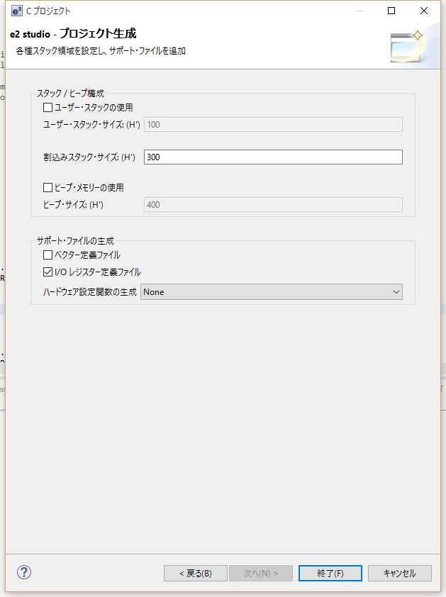
いつも通りにプロジェクトを作成します。
[各種スタック領域を設定し、サポートファイルを追加]の場所で[ユーザー・スタックの使用]と[ヒープ・メモリーの使用]と[ベクター定義ファイル]のチェックを外しプロジェクトを作成します。

新しくできたプロジェクトに前に作成した[FreeRTOS]のフォルダをドラッグ&ドロップでコピーします。
これでFreeRTOSが使えるようになります。
ここにe2studio用のプロジェクトを置いておきます。
OS部を分離すると新しいプロジェクトに簡単に組み込むことができます。
いつも通りにプロジェクトを作成します。
[各種スタック領域を設定し、サポートファイルを追加]の場所で[ユーザー・スタックの使用]と[ヒープ・メモリーの使用]と[ベクター定義ファイル]のチェックを外しプロジェクトを作成します。

新しくできたプロジェクトに前に作成した[FreeRTOS]のフォルダをドラッグ&ドロップでコピーします。


これでFreeRTOSが使えるようになります。
ここにe2studio用のプロジェクトを置いておきます。
秋月電子通商で販売しているAE-RX210ボードでリアルタイムOSのFreeRTOSを動かしてみました。 環境はe2 studio上でRXCです。
今回はOS部分をきれいに分離し新しプロジェクトに組み込み安くしました。ファイルとフォルダの構成を次に示します。
画面上ではこのようになります。
変更・新規作成したファイルを次に示します。
ApplicationHook.c(新規作成)
reset_program.c
main.c
今回はOS部分をきれいに分離し新しプロジェクトに組み込み安くしました。ファイルとフォルダの構成を次に示します。
[src] +---- iodefine.h <-- ウイザードで自動作成 +---- typedefine.h <-- ウイザードで自動作成 +---- dbsct.c <-- ウイザードで自動作成 +---- main.c <-- ウイザードで自動作成 | +-----[FreeRTOS] +------ croutine.h +------ deprecated_definitions.h +------ event_groups.h +------ FreeRTOS.h +------ list.h +------ mpu_wrappers.h +------ portable.h +------ projdefs.h +------ queue.h +------ semphr.h +------ StackMacros.h +------ task.h +------ timers.h +------ croutine.c +------ event_groups.c +------ list.c +------ queue.c +------ tasks.c +------ timers.c | +------ [portable] +------ FreeRTOSConfig.h +------ portmacro.h +------ stacksct.h <-- 移動 +------ vect.h <-- 移動 +------ ApplicationHook.c <-- 新規作成 +------ heap_2.c +------ hwsetup.c <-- 変更 +------ interrupt_handlers.c <-- 移動 +------ port.c +------ reset_program.c +------ vector_table.c
画面上ではこのようになります。

変更・新規作成したファイルを次に示します。
ApplicationHook.c(新規作成)
/* * タスク切り替え用のタイマのスタートと各種フック関数 * * サンプルではmain関数と同じファイルに記述してあったがこのファイルに移動させた */ /* Hardware specific includes. */ #include "../../iodefine.h" /* Kernel includes. */ #include "../FreeRTOS.h" #include "../task.h" #include "../queue.h" /* This variable is not used by this simple Blinky example. It is defined purely to allow the project to link as it is used by the full build configuration. */ volatile unsigned long ulHighFrequencyTickCount = 0UL; /*-----------------------------------------------------------*/ /* A callback function named vApplicationSetupTimerInterrupt() must be defined to configure a tick interrupt source, and configTICK_VECTOR set in FreeRTOSConfig.h to install the tick interrupt handler in the correct position in the vector table. This example uses a compare match timer. It can be into any FreeRTOS project, provided the same compare match timer is available. */ void vApplicationSetupTimerInterrupt( void ) { /* Enable compare match timer 0. */ SYSTEM.PRCR.WORD = 0x0A502; MSTP( CMT0 ) = 0; SYSTEM.PRCR.WORD = 0x0A500; /* Interrupt on compare match. */ CMT0.CMCR.BIT.CMIE = 1; CMT0.CMCR.BIT.CKS = 0; // CLK = PCLK/8 /* Set the compare match value. */ CMT0.CMCOR = ( unsigned short ) ( ( ( configPERIPHERAL_CLOCK_HZ / configTICK_RATE_HZ ) -1 ) / 8 ); /* Divide the PCLK by 8. */ CMT0.CMCR.BIT.CKS = 0; /* Enable the interrupt... */ _IEN( _CMT0_CMI0 ) = 1; ICU.IER[IER_CMT0_CMI0].BIT.IEN_CMT0_CMI0 = 1; //Enable CMIE /* ...and set its priority to the application defined kernel priority. */ _IPR( _CMT0_CMI0 ) = configKERNEL_INTERRUPT_PRIORITY; ICU.IPR[IPR_CMT0_CMI0].BYTE = configKERNEL_INTERRUPT_PRIORITY; // Set interrupt priority level /* Start the timer. */ CMT.CMSTR0.BIT.STR0 = 1; } /*-----------------------------------------------------------*/ /* If configUSE_MALLOC_FAILED_HOOK is set to 1 in FreeRTOSConfig.h, then this function will be called if pvPortMalloc() returns NULL because it has exhausted the available FreeRTOS heap space. See http://www.freertos.org/a00111.html. */ void vApplicationMallocFailedHook( void ) { for( ;; ); } /*-----------------------------------------------------------*/ /* If configCHECK_FOR_STACK_OVERFLOW is set to either 1 or 2 in FreeRTOSConfig.h, then this function will be called if a task overflows its stack space. See http://www.freertos.org/Stacks-and-stack-overflow-checking.html. */ void vApplicationStackOverflowHook( TaskHandle_t pxTask, char *pcTaskName ) { for( ;; ); } /*-----------------------------------------------------------*/ /* If configUSE_IDLE_HOOK is set to 1 in FreeRTOSConfig.h, then this function will be called on each iteration of the idle task. See http://www.freertos.org/a00016.html */ void vApplicationIdleHook( void ) { /* If this is being executed then the kernel has been started. Start the high frequency timer test as described at the top of this file. This is only included in the optimised build configuration - otherwise it takes up too much CPU time and can disrupt other tests. */ } /*-----------------------------------------------------------*/
reset_program.c
/***************************************************************/ /* */ /* PROJECT NAME : FreeRTOS02 */ /* FILE : reset_program.c */ /* DESCRIPTION : Reset program */ /* CPU SERIES : RX200 */ /* CPU TYPE : RX210 */ /* */ /* This file is generated by e2 studio. */ /* */ /***************************************************************/ /********************************************************************* * * Device : RX/RX200 * * File Name : resetprg.c * * Abstract : Reset Program. * * History : 1.00 (2010-12-17) * : 1.10 (2011-02-21) * : 1.11 (2011-06-20) * : 1.20 (2014-09-18) * : 1.21 (2014-10-22) * * NOTE : THIS IS A TYPICAL EXAMPLE. * * Copyright (C) 2010 (2011-2014) Renesas Electronics Corporation. and * Renesas Solutions Corp. All rights reserved. * *********************************************************************/ #include <machine.h> #include <_h_c_lib.h> //#include <stddef.h> // Remove the comment when you use errno //#include <stdlib.h> // Remove the comment when you use rand() #include "../../typedefine.h" // Define Types #include "stacksct.h" // Stack Sizes (Interrupt and User) extern void HardwareSetup( void ); #ifdef __cplusplus extern "C" { #endif void PowerON_Reset_PC(void); void main(void); #ifdef __cplusplus } #endif //#ifdef __cplusplus // Use SIM I/O //extern "C" { //#endif //extern void _INIT_IOLIB(void); //extern void _CLOSEALL(void); //#ifdef __cplusplus //} //#endif #define PSW_init 0x00010000 // PSW bit pattern #define FPSW_init 0x00000000 // FPSW bit base pattern //extern void srand(_UINT); // Remove the comment when you use rand() //extern _SBYTE *_s1ptr; // Remove the comment when you use strtok() //#ifdef __cplusplus // Use Hardware Setup //extern "C" { //#endif //extern void HardwareSetup(void); //#ifdef __cplusplus //} //#endif //#ifdef __cplusplus // Remove the comment when you use global class object //extern "C" { // Sections C$INIT and C$END will be generated //#endif //extern void _CALL_INIT(void); //extern void _CALL_END(void); //#ifdef __cplusplus //} //#endif #pragma section ResetPRG // output PowerON_Reset to PResetPRG section #pragma entry PowerON_Reset_PC void PowerON_Reset_PC(void) { #ifdef __RXV2 set_extb(__sectop("EXCEPTVECT")); #endif set_intb(__sectop("C$VECT")); #ifdef __FPU #ifdef __ROZ // Initialize FPSW #define _ROUND 0x00000001 // Let FPSW RMbits=01 (round to zero) #else #define _ROUND 0x00000000 // Let FPSW RMbits=00 (round to nearest) #endif #ifdef __DOFF #define _DENOM 0x00000100 // Let FPSW DNbit=1 (denormal as zero) #else #define _DENOM 0x00000000 // Let FPSW DNbit=0 (denormal as is) #endif set_fpsw(FPSW_init | _ROUND | _DENOM); #endif _INITSCT(); // _INIT_IOLIB(); // Use SIM I/O // errno=0; // Remove the comment when you use errno // srand((_UINT)1); // Remove the comment when you use rand() // _s1ptr=NULL; // Remove the comment when you use strtok() HardwareSetup(); // Use Hardware Setup nop(); // _CALL_INIT(); // Remove the comment when you use global class object set_psw(PSW_init); // Set Ubit & Ibit for PSW // chg_pmusr(); // Remove the comment when you need to change PSW PMbit (SuperVisor->User) main(); // _CLOSEALL(); // Use SIM I/O // _CALL_END(); // Remove the comment when you use global class object brk(); }
main.c
/* Hardware specific includes. */ #include "iodefine.h" /* Kernel includes. */ #include "FreeRTOS/FreeRTOS.h" #include "FreeRTOS/task.h" #include "FreeRTOS/queue.h" void vTask1(void *pvParameters) { while(1) { PORTC.PODR.BIT.B1 = ~PORTC.PODR.BIT.B1; vTaskDelay(100/portTICK_PERIOD_MS); } } void vTask2(void *pvParameters) { while(1) { PORTC.PODR.BIT.B2 = ~PORTC.PODR.BIT.B2; vTaskDelay(200/portTICK_PERIOD_MS); } } void vTask3(void *pvParameters) { while(1) { PORTC.PODR.BIT.B3 = ~PORTC.PODR.BIT.B3; vTaskDelay(300/portTICK_PERIOD_MS); } } void main(void) { /* Turn all LEDs off. */ PORTC.PDR.BYTE = 0xFF; //ポートC出力 PORTC.PODR.BYTE = 0xFF; //初期値 xTaskCreate(vTask1,"Task1",100,NULL,1,NULL); xTaskCreate(vTask2,"Task2",100,NULL,1,NULL); xTaskCreate(vTask3,"Task3",100,NULL,1,NULL); /* Create the queue. */ vTaskStartScheduler(); /* If all is well the next line of code will not be reached as the scheduler will be running. If the next line is reached then it is likely that there was insufficient heap available for the idle task to be created. */ for( ;; ); }