goo blog サービス終了のお知らせ 

Fiber Optic Tech

Sharing various fiber optic news, inforamtion, topics, etc.

Why Is Fiber Optic Technology 'Faster' than Copper?

2017-02-13 17:04:58 | Fiber Optic Cable

The deployment of fiber optics in telecommunications and wide area networking has been common for many years, but more recently fiber optics have become increasingly prevalent in industrial data communications systems as well. Fiber optic technology uses pulses of light to carry data along strands of glass or plastic. It's the technology of choice for the government's National Broadband Network (NBN) and data centers, which promises to deliver next-generation 200G and 400G Ethernet speeds.
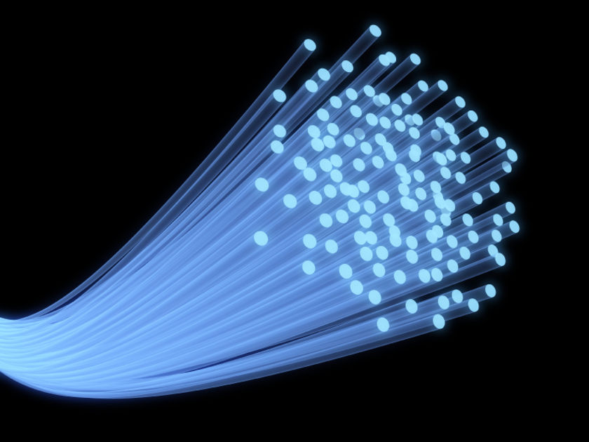
fiber optic technology

When talking about 'speed', we were actually talking about throughput (or capacity) — the amount of data you can transfer per unit time, says Associate Professor Robert Malaney from the University of New South Wales, School of Electrical Engineering and Telecommunications.

And fiber optics can definitely transfer more data at higher throughput over longer distances than copper wire. For example, a local area network using modern copper lines can carry 3000 telephone calls all at once, while a similar system using fiber optics can carry over 31,000.

So what gives it the technical edge over copper wires? Traditional copper wires transmit electrical currents, while fiber optic technology sends pulses of light generated by a light emitting diode or laser along optical fibers.

In both cases you're detecting changes in energy, and that's how you encode data. With copper wires you're looking at changes in the electromagnetic field, the intensity of that field and perhaps the phase of the wave being sent down a wire. With fiber optics, a transmitter converts electronic information into pulses of light — a pulse equates to a one, while no pulse is zero. When the signal reaches the other end, an optical receiver converts the light signal back into electronic information.

The throughput of the data is determined by the frequency range that a cable will carry — the higher the frequency range, the greater the bandwidth and the more data that can be put through per unit time. And this is the key difference — fiber optic cables have much higher bandwidths than copper cables (eg. cat5e copper cable).

"Optical fiber can carry much higher frequency ranges — note that light is a very high frequency signal — while copper wire attenuates or loses signal strength at higher frequencies," says Malaney.

Also, fiber optic technology is far less susceptible to noise and electromagnetic interference than electricity along a copper wire.

"You can send the signal for over 200 km without any real loss of quality while a copper cable signal suffers a lot of degradation over that distance," says Malaney.

As well as a significant increase in connection speed, fiber optic networks offer a tremendous capacity to keep up with any new technological advances. Once the basic fiber optic infrastructure is in place, it can be rearranged and the end point electronics upgraded when necessary, to deliver even higher capacity. It can do this far more effectively than existing wireless or copper based systems.

In terms of its serviceable lifetime, glass (from which fiber optic cable is made) is long lasting, stronger than copper and more able to retain its transmission properties after physical stress such as weight strain, or even attack by rats and cockatoos. We install fiber differently from copper: in good quality coatings, inside ducts, or in the case of newer systems, encased entirely by electrical transmission wires.

For applications where signal security is a concern, fiber optic technology is an excellent solution. Fiber optic cables do not generate electromagnetic fields that could be picked up by external sensors. It is also more difficult to 'steal' signals by spicing into optical fibers than it might be with conventional copper wiring.


Guideline to Choose the Right Fiber Optic Cables

2016-12-08 14:04:38 | Fiber Optic Cable

It’s well-known that fiber optics is the way most of the IT infrastructure service companies currently transmit information. It makes sense if you bear in mind that it allows information and data to travel at greater speeds, through greater distances, and in never-before-seen bundles.

If you plan to enhance the build-out of your network through fiber optics, start by doing an in-depth assessment of your current and future needs. Knowing for sure how your networks will be used and for what is essential for this evaluation since it will allow you to properly and accurately select the type of fiber you might need depending on the application. Some key points to consider when selecting the fiber optic cable that best fits your needs are:

Distances of Transmission

You must be fully cognizant of the distances that the information you will handle must travel. This is crucial in determining what type of cable best suits you. Fiber optic cables are the wisest choice over copper cables which have been traditionally used until recently. It can most definitely support many further distances of input travel than its metal counterpart but the exact distance is difficult to determine as it is limited by a plurality of factors. This is a vital issue for optical communications since it prides itself in being super-fast (as it indeed is) putting data transmission distance under the spotlight.

LC fiber

The signal transmitting the information from point A to point B may possibly weaken if the distance is very long. There are many methods that can be applied and components that can be used to diminish the limitations inflicted by optical transmission distance.

Bandwidth Requirements

Basically, the amount of data or information that can be transmitted through a cable in a fixed or given amount of time is called bandwidth. If it's referring to a website, for example, bandwidth determines the quantity of information and the level of traffic that can transfer between the site, its users, and the Internet as a whole which is why web hosting companies are prone to offer maximum levels of bandwidth as part of their hosting packages.

Network architecture

The way your entire network (hardware, software, communication and connectivity protocols and modes of transmission) is laid out should be taken into consideration when selecting your fiber optics.

Types of Fiber Optic Cables

There are two types of well–known optical fiber cables and each has their own set of unique qualities and characteristics: single-mode and multi-mode.

Single mode optical fiber usually has an 8.3-micron diameter core and makes use of laser technology and light to send and receive data. A micron is a unit of measure equal to 1 millionth of a meter. So you can picture it: one strand of human hair has a diameter of more or less 100 microns.

singlemode-cable-fiber-optic-os1-os2

So single mode fibers have the ability to carry information for miles without losing too many data which makes it ideal for companies that offer services such as cable and telephone providers.

Transmission distance is affected by chromatic dispersion because the core of single-mode fibers is much smaller than that of multimode fibers. And it is also the reason why single-mode fiber can have longer transmission distance than multimode fiber. If you need to handle large amounts of data with the least dispersion, single mode fiber might be your best choice. Just take into consideration that these fibers are noticeably more expensive than multimode ones since the technology used is a bit more sophisticated.

Multimode optical fiber, as its very name indicates, allows the signal to travel through different pathways or modes that are placed inside of the cable’s core. For these types of fibers, the transmission distance is largely affected by modal dispersion.

multimode-cable-fiber-optic-om1-om2-om3-om4

Due to the fact that the fibers in multimode cables have imperfections, the optical signals are not able to arrive at the same time causing a delay between the fastest traveling modes and the slowest ones, which in turn causes the dispersion and limits multimode fiber performance.

Multimode fibers can be found in 4 different presentations identified with the acronym OM which stands for optical multi-mode and varies according to performance criteria determined by ISO/IEC 11801 standards. These presentations are OM1, OM2, OM3, and OM4.

Conclusion

Choosing the proper fiber optic cable to fit your needs may seem like a daunting task but it really isn’t. Just invest some time to do the necessary research beforehand and you'll save yourself a lot of time and trouble as well as money.


Can High Density and Easy Cable Management Go Hand in Hand?

2016-11-12 10:26:38 | Fiber Optic Cable

New technology develops in networking, such as 40G, 100G and 400G Ethernet solutions, which means that data center administrators have new challenges: maintaining high availability, reducing costs, and seeking future proof applications. When pursuing maximal density, capacity and performance, can cable management go hand in hand? This passage will give you the answer.

In fact, high-density fiber connectivity products are the key to making high density a reality without sacrificing streamlined, cost-efficient cable management. Here are the HD series fiber connectivity components from FS.COM which ensure easy cable management along the way.

High-Density Patch Panels

The right high-density patch panel can provide fast, intuitive and easy deployment of high-density interconnects and cross-connects in data centers and LANs – all while conserving valuable rack space. Angled styles can also facilitate cable management practices as compared to standard patch panels.

With the wide deployment of 40G and 100G high speed networks. MPO/MTP breakout patch panel may be an ideal solution for this high-density installation. Deploying high-density patch panels has many advantages. It simplifies the cabling deployment by running short fiber patch cables from your SAN or network switch up to the fiber patch panel. Much space can also be saved in data centers by mounting more cables into a smaller space. Installation is easier since no tools are required to install cassettes in the patch panels, and push-pull tabs are used to ease the difficulty of cable connections in the patch panels.

Fiber Optic Enclosures

Reconfigurable/adjustable panels with various mounting and attachment features can ensure that the patch panel works with your data center configuration without having to buy new components.

Superior port access with increased density can provide up to a 50% reduction in RU (rack unit) space. Also look for housing with an intuitive, modular design – this leads to fewer components and offers a single system that supports a variety of port counts and configurations. Ports should be identified through clear, visible labeling.

Highly accessible sliding and tilting drawers speed up field termination; drawers that can be removed without tools can also reduce installation time. If you’re looking for a pre-terminated solution, housing with simple fixed shelves and cassettes keep deployment time to a minimum.

Solutions that offer support for both legacy ST and SC and modern LC and MPO applications help support cost-effective migration to 40G and 100G applications with only a simple cassette or adapter frame change.

High-Density Patch Cords

High-Density patch cords feature a new pull tab which allows patch cord removal even in highly populated patch panels without the need for a special tool.

Due to space constraints, data centres require high density solutions. With traditional patch cords the operational efficiency is reduced since the latch of the patch cord is above the connector. In dense areas it is often impossible to reach: an additional removal tool is required. With the new pull tab design the latch is extended to the space behind the connector. In this area the pull tab can be easily accessed and the patch cord is released with a simple pull.

Patch cords should also be marked and easily accessible for faster fiber type identification. A great example: Fiberstore uses green on OM3/OM4 cable, adapters and connector bodies and blue on OS2 cable, adapters and connector, making it easy to tell the difference between single mode and multimode fibers.

High-Density Trunks

High-density trunks allow tighter trunk cable bends for slack storage and routing. When you can find high-density trunks that offer smaller/lighter transitions, less space is consumed and installation is easier. Cable pulling and cable management are improved when a cable with a smaller overall diameter is used.

Look for a staggered, ergonomic design that allows easy access to connectors to install MPO trunks. A pulling eye can add efficiency and security when it’s time to move the trunks through densely packed ducts and conduits.

FS.COM HD Fiber Connectivity Solutions

FS.COM HD fiber connectivity solution is your quality choice for easier cable management and high density cabling in data center. Our line of high-density fiber connectivity solutions support easy, streamlined cable management which will save installation time and labor costs to a large extent.


Upgrade Your Network With OM3/OM4 Multimode Fiber Cables

2016-08-25 15:14:22 | Fiber Optic Cable

With each passing year, demand for higher data rates in data center environments increases. More and more sophisticated equipment is introduced into the marketplace and more users need access to data center services. These new increased data rates will require cleaner signals for transmission of laser pulses on multimode fiber. Currently, there are two types of multimode fiber jumpers—OM3 and OM4 patch cables. This article will explain how they provide optimum choices to enhance network reliability and performance in great detail.

OM3 and OM4 Patch Cable Overview

OM here refers to optical multimode, and multimode fiber has been widely employed in data centers nowadays since it presents a cost efficient option for short distance transmission. OM3 and OM4 are both laser-optimized multimode fibers with 50/125um core, which are designed for use with 850nm VCSELS (vertical-cavity surface-emitting laser) and are developed to accommodate faster networks such as 10, 40 and 100 Gbps. Compared with OM1 and OM2 patch cables, OM3 and OM4 patch cables are undoubtedly more suitable for today’s demanding networks as they enable data to transport at higher rate and longer distance.

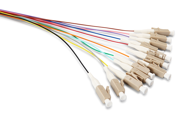
LC fiber cable

The Advantages of OM3 and OM4 Patch Cable

The IEEE 802.3ba 40/100G Ethernet Standard was ratified in June 2010, which provides specific guidance for 40/100G transmission with multimode and single-mode fibers. According to the standard, OM3 and OM4 are the only multimode fibers included in it. And they are massively applied to upgrade the legacy infrastructure, especially for migrating to high-density networks. So, how can we exactly benefit from OM3/OM4 patch cables?

  • Higher Bandwidth First and foremost, bandwidth is the main reason why OM3 and OM4 patch cables are used for network upgrades. OM3 and OM4 patch cables are optimized for 850nm transmission and have a minimum 2000 MHz∙km and 4700 MHz∙km effective modal bandwidth (EMB). Compared with OM1 and OM2 patch cables with the maximum 500 MHz∙km, advantages of OM3 and OM4 are obvious. With a connectivity solution using OM3 and OM4 cables that have been measured using the minimum EMB calculate technique, the optical infrastructure deployed in the data center will meet the performance criteria set by IEEE for bandwidth.
  • Longer Transmission Distance The impact that transmission distance of fiber patch cables has on the data center cabling cannot be overestimate. And the manageability and flexibility will increase parallelly with longer transmission distance. OM3 and OM4 patch cables can support longer transmission distance compared with traditional multimode fibers. Generally OM3 fibers can run 40/100 Gigabit at 100 meters and OM4 fibers can run 40/100 Gigabit at 150 meters.
  • Lower Insertion Loss Insertion loss has always been an essential factor to be considered during data center cabling. This is because the total connector loss within a system channel impacts the ability to operate over the maximum supportable distance for a given data rate. As total connector loss increases, the supportable distance at that data rate decreases. OM3 patch cable is specified to a 100m distance with a maximum channel loss of 1.9dB, which includes a 1.5dB total connector loss budget. And OM4 patch cable is specified to a 150m distance with a maximum channel loss of 1.5 dB, including a total connector loss budget of 1.0 dB. In this way, OM3 and OM4 patch cables help to achieve maximum flexibility and longer supportable transmission distance.
OM3 Patch Cable vs. OM4 Patch Cable

Apparently, OM3 and OM4 patch cables offer us an ideal alternative to upgrade the existing infrastructure. A question may occur to us is to determine which one is better. Well, it depends on several factors. Among which the applications and the total costs always serve as major ones. Due to the difference in the construction of fiber cable, OM4 patch cable has better attenuation and higher bandwidth of longer distance. Moreover, the cost for OM4 is higher than OM3. As 90% of all data centers have their runs under 100 meters, OM3 may be a better choice. However, considering future growth, the overall cost would come down with the increasing demand. In this case, OM4 might be the most viable option.

Conclusion

OM4 fiber has been on the market since 2005, sold as premium OM3 or OM3 fiber. The OM4 designation standardizes the nomenclature across all manufacturers so that the customer has a clearer idea of the product that they are purchasing. OM4 is completely backwards compatible with OM3 fiber and shares the same distinctive aqua jacket. With either OM3 or OM4 patch cable, you are capable of upgrading the existing infrastructure to achieve more reliable and flexible network performance. When choosing between these two types of patch cables, you’d better make the decision according to your particular needs.


Picking the Right Fiber Connector – UPC or APC?

2016-08-15 16:38:30 | Fiber Optic Cable

You may often read things like LC/APC simplex singlemode connector or SC/UPC simplex singlemode connector. When looking at this LC to LC patch cable page, we can also find descriptions like “LC UPC to LC UPC duplex 10G OM4 multimode fiber optic patch cable”. What do all those words mean? Specifically UPC and APC. In fact, UPC and APC are two polish types of fiber ferrules. This article will help you explore the world of UPC and APC to decide which one is suitable for your network.

What Is UPC and APC?

To help us better understand all this jargon, let’s look back at why the original Flat Fiber Connector evolved into the Physical Contact (PC) connector and then onto UPC and APC.

Ultra Physical Contact (UPC) is building on the convex end-face attributes of the Physical Contact (PC), but utilizing an extended polishing method creates an even finer fiber surface finish: bringing us the UPC connector. This results in a lower back reflection (ORL) than a standard PC connector, allowing more reliable signals in digital TV, telephony and data systems, where UPC today dominates the market.

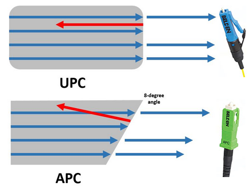
The end face of Angled Physical Contact (APC) connector is precisely polished at an 8-degree angle to the fiber cladding so that most return loss is reflected into the cladding where it cannot interfere with the transmitted signal or damage the laser source. But it is extremely difficult to field terminate an APC connector at 8 degrees with any consistent level of success. Therefore, if an APC connector is damaged in the field, it should be replaced with a factory terminated APC connector.

UPC and APC

Difference Between UPC and APC
  • End Faces — As we have discussed before, UPC connectors are polished with no angle, but APC connectors is polished at an 8-degree angle.
  • Ways of Light Reflection — Their different polish end faces directly lead to their differences in ways of light reflection. Any reflected light is reflected straight back towards the light source if an UPC connector is used. But the APC connector causes reflected light to reflect at an angle into the cladding instead of straight back toward the source.
  • Return Loss — Since their light reflection patterns are varied, their levels of return loss are also different. APC connector offers lower return loss of -65 dB than UPC of -50 dB. As a matter of fact, connectors can achieve better matching performance if return loss is lower.
  • Connector Color — This is the most obvious difference that can be seen from the surface. UPC connector usually has a blue body while APC connector has a green body.
Picking the Right Physical Contact Connector

Looking at current technology, it’s clear that all of the connector end-face options mentioned above have a place in the market. Indeed, if we take a sidestep across to Plastic Optical Fiber (POF) applications, this can be terminated with a sharp craft knife and performance is still deemed good enough for use in the high-end automotive industry. When your specification also needs to consider cost and simplicity, not just optical performance, it’s hard to claim that one connector beats the others.

Therefore when it comes to fiber optic jumpers, whether you choose UPC or APC will depend on your particular need. With those applications that call for high precision optical fiber signaling, APC should be the first consideration, but less sensitive digital systems will perform equally well using UPC.