Fiber Optic Tech

Sharing various fiber optic news, inforamtion, topics, etc.

Single-mode Fiber Patch Cable vs. Multimode Fiber Patch Cable

2016-05-31 10:44:07 | Fiber Optic Cable

Fiber patch cable, also known as fiber optic jumper or fiber optic patch cord, is designed to interconnect or cross connect fiber networks within structured cabling systems. The connectors capped at either end of the fiber patch cable allow it to be rapidly and conveniently connected to an optical switch, cable television (CATV) or other telecommunication equipment. Depending on transmission medium, the fiber patch cable can be classified into single-mode fiber patch cable and multimode fiber patch cable.

What Is Single-mode Fiber Patch Cable

Single-mode fiber patch cables or single mode fiber jumpers are generally yellow. They are composed of one fiber optic cable terminated with single mode fiber optic connectors at both ends. It is usually used for connections over large areas, such as college campuses and cable television networks. Compared with multimode fiber patch cable, single-mode fiber patch cable have a higher bandwidth. The following figure shows the common single-mode fiber patch cable which is with blue connectors at both ends.

single mode fiber jumpers

What Is Multimode Fiber Patch Cable

Multimode fiber patch cable, which is generally orange or grey, is composed of a fiber optic cable terminated with multimode fiber optic connectors at both ends. Its connectors are generally cream or black (as shown below). Due to the high capacity and high reliability, multi-mode fiber patch cables are a good choice for transmitting data and voice signals over shorter distances. They are typically used for data and audio/visual applications in local-area networks and connections within buildings.

multimode patch cable

Difference Between Single-mode and Multimode Fiber Patch Cables

The main difference between single-mode and multimode patch cable is the size of their respective cores.

Single-mode fiber optic patch cables use 9/125 (“9″ represents the diameter of the core, and “125” represents the diameter of the cladding) micron bulk single-mode fiber cables. The most common type of single-mode fiber has a core diameter of 8 to 10 microns. In single-mode cables, light travels toward the center of the core in a single wavelength, allowing the signal to travel faster and over longer distances without a loss of signal quality than is possible with multimode cabling.

Multimode fiber patch cables use 62.5/125 (“62.5″ represents the diameter of the core, and “125” represents the diameter of the cladding) micron or 50/125 (“50″ represents the diameter of the core, and “125” represents the diameter of the cladding) micron multimode fiber cables. In other words, the core of the multimode fiber patch cable is either 50 or 62.5 microns. Compared with single-mode cable, the larger core of the multimode cable gathers more light, and this light reflects off the core and allows more signals to be transmitted. Although it is more cost-effective than single-mode cable, the multimode cabling does not maintain signal quality over long distances.

In conclusion, both single-mode fiber patch cable and multimode fiber patch cable have their respective applications. They can be used in computer work station to outlet and patch panels or optical cross connect distribution center. Whether to choose single mode or multimode depends on many factors, like the applications, the distance requirement, the budge, etc.


Optical Modules for 25 Gigabit Ethernet

2016-05-26 11:31:56 | 25 Gigabit Ethernet

Although the widely acknowledged Ethernet speed upgrading path was 10G-40G-100G, web-scale data centers and cloud based services need servers with above 10GbE capability and cost sensitive for nearer-term deployment. It indicates that the latest path for server connection will be 10G-25G-100G with potential for future upgrading to 400G. But why 25G? Because moving from 10G to 40G is a big jump and it turns out that the incremental cost of 25G silicon over 10G is not that great. This new 25 Gigabit Ethernet standard will require improved cables and transceiver modules capable of handling this additional bandwidth. It is just under this circumstance that QSFP28 and SFP28 for 25 Gigabit Ethernet are promoted.

25GbE Ethernet—An Emerging Standard

25 Gigabit Ethernet (25GbE) has passed the first hurdle in the IEEE standards body with a successful Call for Interest (CFI) in July, 2014. It is a proposed standard for Ethernet connectivity that will benefit cloud and enterprise data center environments. 25GbE leverages technology defined for 100 Gigabit Ethernet implemented as four 25-Gbit/s lanes (IEEE 802.3bj) running on four fibers or copper pairs.

25GbE

Significant Performance Benefits—25G Over 40G

The value of 25GbE technology is clear in comparison to the existing 40GbE standard. Obviously, 25GbE technology provides greater port density and a lower cost per unit of bandwidth for rack server connectivity. For applications that demand substantially higher throughputs to the endpoint, there exists 50GbE—using only two lanes instead of four—as a superior alternative to 40GbE in both link performance and physical lane efficiency.

The proposed 25GbE standard delivers 2.5 times more performance per SerDes lane using twinax copper wire than that available over existing 10G and 40G connections. A 50GbE link using two switch/NIC SerDes lanes running at 25 Gb/s each delivers 25% more bandwidth than a 40GbE link while needing just half the number (four) of twinax copper pairs. Therefore, a 25GbE link using a single switch/NIC SerDes lane provides 2.5 times the bandwidth of a 10GbE link over the same number of twinax copper pairs are used in today’s SFP+ direct-attach copper (DAC) cables.

Maybe the most outstanding benefit of 25GbE technology to data-center operators is maximizing bandwidth and port density within the space constraints of a small 1U front panel. It also leverages single-lane 25Gb/s physical layer technology developed to support 100GbE.

Cloud Will Drive to QSFP28 and SFP28

QSFP28 is used for 4x25GE and SFP28 is used for a single 25GE port. SFP28 module, based on the SFP+ form-factor, supports the emerging 25G Ethernet standard. It enables error-free transmission of 25Gb/s over 100m of OM4 multi-mode fiber and a new generation of high-density 25 Gigabit Ethernet switches and network interface cards, facilitating server connectivity in data centers, and a conventional and cost-effective upgrade path for enterprises deploying 10 Gigabit Ethernet links today in the ubiquitous SFP+ form factor. The QSFP28 (25G quad small form-factor pluggable) transceiver and interconnect cable is a high-density, high-speed product solution designed for applications in the data center and networking markets. The interconnect offers four channels of high-speed signals with data rates ranging from 25 Gbps up to potentially 40 Gbps, and will meet 100 Gbps Ethernet (4x25 Gbps) and 100 Gbps 4X InfiniBand Enhanced Data Rate (EDR) requirements. The following shows a QSFP28-SR4 module and a 10GBASE-SR SFP+ module (MA-SFP-10GB-SR).

MA-SFP-10GB-SR

Conclusion

The dominant next-generation server connection speed is going to be 25G as it providing a cost competitive longer reach option for mainstream customers. FS.COM has already introduced cost-effective QSFP28 modules, QSFP28 to QSFP28 cable as well as SFP28 cable. With advanced OEM technology and strict cost control, we can help you save more than 30%~50% off on the cost of the QSFP28 modules.


10GBASE-T Will Be the Best Choice for 10GbE Data Center Cabling

2016-05-24 15:20:16 | 10 Gigabit Ethernet

Over the past few decades, large enterprises have been migrating data center infrastructures from 100MB Ethernet to 1/10 Gigabit Ethernet (GbE) to support higher bandwidth, mission critical applications. However, many mid-market companies found themselves restricted from this migration to 10GbE technology due to cost, low port density and high power consumption. For many of those companies, the explosive growth of technologies, data and applications is severely taxing existing 1GbE infrastructures and affecting performance. So it’s high time for them to upgrade the data center to 10GbE. With so many 10GbE interfaces options such as CX4, SFP fiber module, SFP+ Direct Attach Copper (DAC), and 10GBASE-T offered, which one is your choice? This article will give you the answer.

Data Center Needs to Upgrade to 10GbE

As server consolidation increases through virtualization in the data center, the resulting data demand has exceeded traditional 1Gb/s throughput capabilities. Gigabit Ethernet connections can handle the bandwidth requirements of a single physical server, but they are inadequate to support virtualized server-consolidation scenarios, or multiple traffic types during peak periods. Today these virtualized servers are typically configured with multiple 1Gb/s ports in order to keep up with the I/O demands. Moving to 10GbE overcomes these 1Gb/s bandwidth limitations by providing more bandwidth and simplifies the network infrastructure by consolidating multiple gigabit ports into a single 10GbE connection.

10GbE deployment

Shortcomings of SFP+ in 10GbE Data Center Cabling

SFP+ has been adopted on Ethernet adapters and switches and supports both copper and fiber optic cables makes it a better solution than CX4, which is the mainstream 10GbE adoption today. However, it has some limitations that will prevent this media from moving to every server. In terms of SFP+ DAC, it is a lower cost alternative to fiber but it can only reach 7 meters. SFP+ fiber can reach both short-range of 300m (e.g. 10GBASE SR SFP) and long-range of 10km, but it is relatively expensive. Besides above, the biggest problem with SFP+ is simply that it is not backward-compatible with the twisted-pair 1GbE broadly deployed throughout the data center. SFP+ connectors and their cabling were not compatible with the RJ-45 connectors used in 1GbE networks. Enterprise customers cannot just start adding SFP+ 10GbE to an existing RJ-45 1GbE infrastructure. New switches and new cables are required, which is a big chunk of change.

10GBASE-T Promotes the Data Center Migration from 1GbE to 10GbE

In 2006, IEEE 802.3an, which specified the use of 10GBASE-T over UTP cabling, which solves the cabling and backward compatibility problems. Because 10GBASE-T is backward-compatible with 1000BASE-T, it can be deployed in existing 1GbE switch infrastructures in the data centers that are cabled with CAT6, CAT6A or above cabling. Seen from the picture below, we can see that 1GbE is still widely used in data center. 10GBASE-T is backwards compatible with 1GbE and thus will greatly promote gradual transitioning from 1GbE deployment to 10GbE.

Besides, the raw cost of the cable itself is far less than either optical fiber or SFP+ DAC cables, and with its extended reach, can be used without the need for a Top-of-Rack switch. This flexibility and compatibility with existing equipment facilitates the transition from 1GbE to 10GbE and makes 10GbE affordable and effective for use across the data center.

Conclusion

10GBASE-T breaks through important cost and cable installation barriers in 10GbE deployment as well as offering investment protection via backwards compatibility with 1GbE networks. Deployment of 10GBASE-T will simplify the networking transition by providing an easier path to migrate to 10GbE infrastructure in support of higher bandwidth needed for virtualized servers. In the future, 10GBASE-T will be the best option for 10GbE data center cabling!


Next-generation Parallel Optical Data Links

2016-05-23 15:00:09 | Fiber Optic Network

Parallel-optical data links are now available and designed into many next-generation telecom/datacom central-office switches and routers. In order to meet the continued growing Internet capacity over the next couple of years, parallel-optical data links are gaining more and more popularity. This article will introduce the next-generation parallel optical data links which will play continuing role in the future network of data communications.

What Is Parallel Optical Link

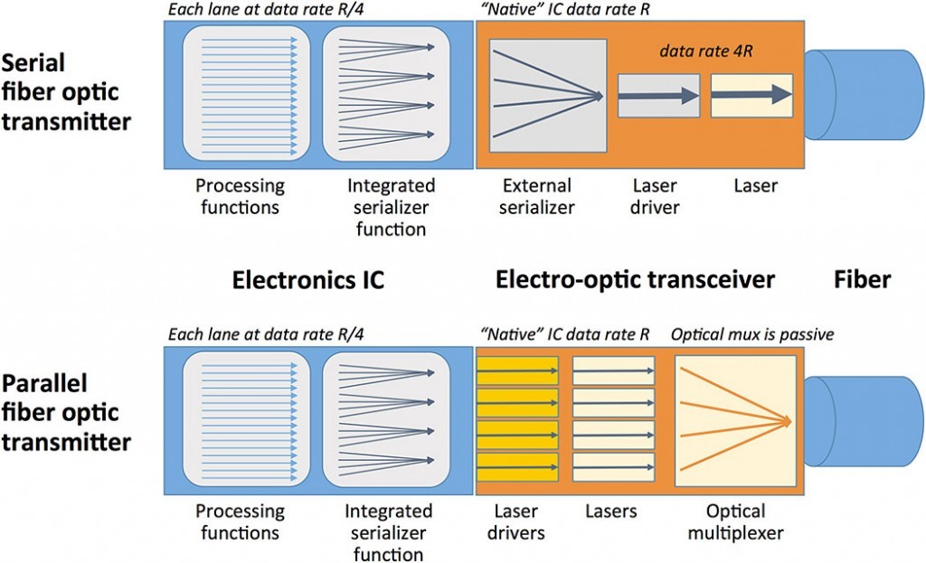
Parallel optical data link is a concept opposite to serial optical data link and also a replacement for many serial data communication links. In the more typical application of parallel optic link, one byte of information is split up into bits. And each bit is coded and sent across the a single fibers. Parallel optic links are often the most cost effective for 40 Gigabit transmission, and can transmit over distances exceeding 100 meters. Serial optical solutions can relieve bandwidth-distance, cable bulk, and EMI limitations of metallic interconnects. However, they still take up significant space and they are somewhat more expensive than copper interconnects. A much less space is possible with parallel optical module (e.g. 40G-QSFP-SR4-INT) rather than with multiple serial modules. Therefore, parallel optical module greatly increases interface density. Parallel optical link modules contain laser arrays, multichannel driver, receiver ICs and fiber-ribbon optical connectors, amortizing packaging costs over several channels.

serial-vs-parallel-optical-transmitter

Key Components of Parallel Optical Links
  • Multifiber Connectors The connector is a critical enabling component, since its design ultimately determines the density, quality, and cost of fiber-optic interconnects. The connectors are most often used for multi-fiber links is the so-called MPO (multi-fiber push-on connector), also known by its most common vendor branded version, the MTP connector. The multifiber connectors trim costs for connector hardware, assembly, and cabling compared to single-fiber connector. This kind of connectors are not only save place for more efficient use of precious system board space, but their smaller port area also help reduce EMI. For various historical reasons, these connectors were standardized in rows of 12 fibers each, which isn’t a good match for data communication systems. Later, MPO/MTP connectors evolve to have 8-fiber row and 16-fiber row. The 40G interface is based on parallel striping of 10 Gbit/s serial channels. If we held up a standard 1 x 12 fiber MPO connector and looked back into the cable, the 4 leftmost fibers are used to transmit data, the middle 4 fibers are unused lanes, and the 4 rightmost fibers are used to receive data. Thus, we have a bidirectional interface with 4 x 10G in each direction. Following the same principle, we can use 10 Gbit/s links to build a duplex 100 Gbit/s channel, but we need an MPO connector with 2 rows of 12 fibers each. We leave the outermost fibers on either end of the rows unused, and use the remaining 10 fibers in the upper row to transmit data, and the remaining 10 fibers in the lower row to receive data.
  • Fiber Cables As data rates increase, link loss budgets and insertion loss will significantly decrease, so if you have plans to re-connectorize your installed fiber cable plant, be sure that the infrastructure is adequate for this application. You’ll also need adapters to fan out the MPO connection into simplex connections which are compatible with existing test and measurement equipment, to verify link performance. This kind of cables include QSFP to SFP+ breakout cable and QSFP+ to QSFP+ direct attach cable.
  • VCSEL-based Link Design The use of low cost VCSEL based laser transmitters is appealing for this application. While the advantages of discrete VCSELs have already placed them into serial link modules, the new parallel link modules will exploit the multichannel advantages of VCSELs arrays in parallel or WDM link modules.
Summary

Although some serial optical links can support high data rates (particularly for multi-data center connectivity or telecommunication systems), parallel optical links are a promising solution for more cost effective, higher data rate links within the data center. At shorter distances, such as within a data center rack or between adjacent racks (perhaps up to 100 meters), parallel optics are cost competitive with copper links. Thus, rather than using single-mode fiber, some laser optimized multi-mode fibers are often used. And an active optical cable allows for tradeoffs between the transmitter, receiver, and fiber parameters. We can also use existing 10 Gbit/s serial link technology and volumes by combining either 4 links to create a 40G channel, or 10 links to create a 100G channel.


Limiting Factors in Fiber Optic Transmissions

2016-05-18 16:38:16 | Fiber Cabling

Fiber-optic communication is a method of transmitting information from one place to another by sending pulses of light through an optical fiber. Compared with copper cable, fiber optic cable can support longer transmission distance, high speed, high bandwidth, etc. However, not everything is perfect. There are still some factors that may influence the transmission distance over fiber cables. This article will introduce the most common factors that limit the data transmission distance.

Fiber Optic Cable Type

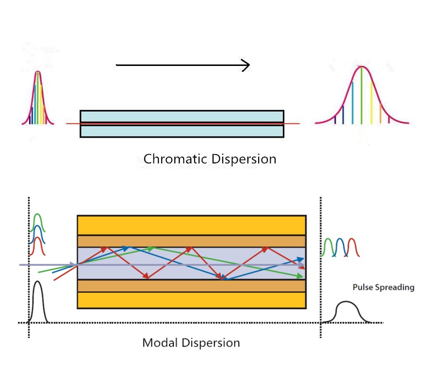
Generally speaking, the maximum transmission distance is limited by dispersion in fiber optic cable. There are two types of dispersion that can affect the optical transmission distance. One is chromatic dispersion, which is the spreading of the signal over time resulting from the different speeds of light rays. The other is modal dispersion representing the spreading of the signal over time resulting from the different propagation mode.

Multimode transmission is largely affected by the modal dispersion, because of the fiber imperfections, these optical signals cannot arrive simultaneously and there is a delay between the fastest and the slowest modes, which causes the dispersion and limits the performance of multimode fiber. For single-mode fiber, it is chromatic dispersion that affects the transmission distance. Because the core of the single-mode fiber optic is much smaller than that of multimode fiber. That’s the main reason why single-mode can transmit signals over longer distance than multimode fiber.

Chromatic Dispersion & Modal-Dispersion

Light Source of Optical Transceiver Module

Like most of the terminals, fiber optic transceiver modules are electronic based. Transceiver modules play the role of EOE conversions (electrics-optics-electrics). The conversion of signals largely depends on an LED (light emitting diode) or a laser diode inside the transceiver, which is the light source of fiber optic transceiver. The light source can also affect the transmission distance of a fiber optic link.

LED diode based transceivers can only support short distances and low data rate transmission. Thus, they cannot satisfy the increasing demand for higher data rate and longer transmission distance. For longer transmission distance and higher data rate, laser diode is used in most of the modern transceivers, such as Cisco QSFP-40G-SR4 QSFP+ transceiver and MA-SFP-10GB-SR SFP+ transceiver. The most commonly used laser sources in transceivers are Fabry Perot (FP) laser, Distributed Feedback (DFB) laser and Vertical-Cavity Surface-Emitting (VCSEL) laser. The main characteristics of these light sources are listed below.

Light Source Transmission Distance Transmission Speed Transmission Frequency Cost
LED Short Range Low Speed Wide Spectral width Low Cost
FP Medium Range High Speed Medium Spectral Width Moderate Cost
DFB Long Range Very High Speed Narrow Spectral Width High Cost
VCSEL Medium Range High Speed Narrow Spectral Width Low Cost
Transmission Frequency

As shown in the above chart, different laser sources support different frequencies. The maximum distance a fiber optic transmission system can support is affected by the frequency at which the fiber optic signal will be transmitted. Generally the higher the frequency, the longer distance the optical system can support. Thus, choosing the right frequency to transmit optical signals is necessary. Generally, multimode fiber system uses frequencies of 850 nm and 1300 nm, and 1300nm and 1550 nm are standard for single-mode system.

Bandwidth

Bandwidth is another important factor that influences the transmission distance. Usually, as the bandwidth increases, the transmission distance decreases proportionally. For instance, a fiber that can support 500 MHz bandwidth at a distance of one kilometer will only be able to support 250 MHz at 2 kilometers and 100 MHz at 5 kilometers. Due to the way in which light passes through them, single-mode fiber has an inherently higher bandwidth than multimode fiber.

Splice and Connector

Splice and connector are the transmission distance decreasing reasons as well. Signal loss occurs when optical signal passes through each splice or connector. The amount of the loss depends on the types, quality and number of connectors and splices.

As a conclusion, the top 5 limiting factors in fiber optic transmission are fiber optic cable type, light source of the optics, frequency, bandwidth, splice and connector. After knowing these factors, we can take measures purposely to increase the transmission distance in real situations. Meanwhile, equipment like optical amplifiers and repeater and are also useful to support longer distance transmission.