Fiber Optic Tech

Sharing various fiber optic news, inforamtion, topics, etc.

In-depth Understanding of Data Center Fiber Cabling

2016-04-01 16:50:33 | 日記

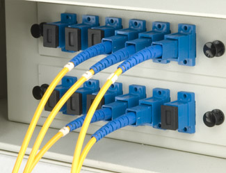
With the rapid development of fiber optic communications, fiber optic cables have become an indispensable component for each data center. They’re playing an important part in transmitting data at fast and reliable speed. Yet many router jockeys don’t get enough exposure to fiber cabling, which leads to a wide variety of confusion, misconceptions, and errors when working with fiber optic networks. The purpose of this post is to help you get an in-depth understanding of these topics related to data center fiber cabling.

Data Centers

Basic Knowledge About Fiber

Fiber cables are internally composed of two layers, the “core” and the “cladding”. They can be classified into two main types: single mode fiber (SMF) and multimode fiber (MMF). When considering the fiber optics for your data center, the most basic thing is to decide between SMF and MMF.

Single mode cable is a single stand of glass fiber with a diameter of 8.3 to 10 microns that has one mode of transmission. Single Mode Fiber with a relatively narrow diameter, through which only one mode will propagate typically 1310 or 1550nm. Carries higher bandwidth than multimode fiber, but requires a light source with a narrow spectral width. Synonyms are mono-mode optical fiber, single mode fiber, single mode optical waveguide, uni-mode fiber. Single mode fiber gives you a higher transmission rate and up to 50 times more distance than multimode, but it also costs more.

Multimode cable is made of glass fibers, with common diameters in the 50-to-100 micron range for the light carry component (the most common size is 62.5).POF is a newer plastic-based cable which promises performance similar to glass cable on very short runs, but at a lower cost. Multimode fiber gives you high bandwidth at high speeds over medium distances. Light waves are dispersed into numerous paths, or modes, as they travel through the cable's core typically 850 or 1300nm. Typical multimode fiber core diameters are 50, 62.5, and 100 micrometers. However, in long cable runs, multiple paths of light can cause signal distortion at the receiving end, resulting in an unclear and incomplete data transmission.

Best Practices For Better Fiber Cabling

Though fiber cabling has distinct benefits compared with copper in regard to transmission, attenuation and electromagnetic interference (EMI), improper practices of fiber cabling may lead bad effect to data transmission. Therefore, we must maintain the best practices when we doing fiber cabling.

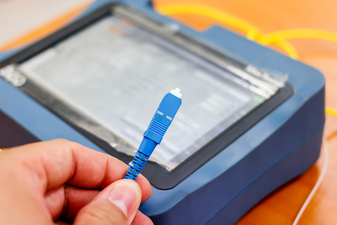
  • Inspection & Cleaning: Usually, we do the inspection with fiber microscope (optical microscope or video microscope). It is easy to use but be sure to follow the instruction. In addition, you must beware of bad habits when you doing cleaning. Because cleaning has been part of fiber maintenance for years, most people have their own approaches for cleaning end-faces. However, beware of bad habits as many have developed in the industry over time. In a word, whatever approach is selected, certain truisms apply to fiber optic end-face inspection and cleaning. Strictly follow the defined working process and principles and consistent inspection and cleaning up front will avoid unexpected and costly downtime in the future.
  • Fiber Bend Radius: There is a reduction in the strength of that signal when a cable is bent. Similarly, fiber optic cables is also as. The bend radius, or measurement of a curve, can determine how strong the data signal will flow. With fiber cabling, there are different specifications for bend radius varying by cable manufacturer and fiber type. There have been many improvements made in this area, including the development of "bend insensitive fiber". A good rule of thumb for determining bend radius during installation is that bend radius equals 10-15 times the outer diameter of the cable jacket.
  • Pulling Fiber: In many cases, fiber cabling must run over long distances. Although fiber optic cabling assemblies are robust and sturdy, it needs to be cautiously used when pulling. It is important to remember that never pull from the connectors because this position is typically the weakest link in pulling strength. In addition, we suggest you to use a pulling sock to reduce strain on critical areas. It is readily available from the related suppliers.
  • Tie-down Points: Tie-down point, here we mentioned, is the area where cable is affixed to patch panels or racks and cabinets to ensure they do not move around. To tie-down the fiber cable properly, you may never use zip ties on fiber optic cable unless there are specific designated areas on the cable to do so. The common and proper way is to use Velcro and never over tighten, as this can crack the fiber and cause failure. The following picture shows us the improper and proper ways to tie-down fiber.
Tie-down points
 
Conclusion

As data rates keep increasing, fiber optic cable will become more necessary in many data center applications. A thorough understanding of the basics will help you work better and more higher efficiency. I hope you will enjoy this article and gain some helps or working inspiration from it. In addition, if you have any requirement about the related products, such the fiber cables, fiber patch cord, fiber patch panel or other fiber optic products, you can contact us directly via sales@fs.com.

Reference: http://www.fs.com/blog/basic-knowledge-tips-of-data-center-fiber-cabling.html


Mode Conditioning Patch Cable Overview

2016-03-31 17:05:29 | 日記
What is Mode Conditioning Patch Cable?

Mode conditioning patch cable, also called mode conditioning patch cord (MCP), is a duplex multimode patch cable that has a small length of single mode fiber at the start of the transmission length. Designed to "condition" the laser launch and obtain an effective bandwidth closer to that measured by the overfilled launch method, the MCP allows for laser transmitters to operate at gigabit rates over multimode fiber without being limited by Differential Mode Delay (DMD). The point is to excite a large number of modes in the fiber, weighted in the mode groups that are highly excited by overfill launch conditions, and to avoid exciting widely separated mode groups with similar power levels. This is achieved by launching the laser light into a single mode fiber, then coupling it into a multimode fiber that is off-center relative to the single mode fiber core.

mode conditioning patch cable

The need for this kind of fiber patch cables is due to the single-mode launch nature of the -LX (1300nm) transceiver modules used for Gigabit Ethernet. These modules have to operate for both single-mode and multimode fibers. Launching a single-mode laser into the center of a multimode fiber can cause multiple signals to be generated that confuse the receiver at the other end of the fiber. These multiple signals, caused by DMD effects, severely limit the cable distance lengths for operating Gigabit Ethernet. A mode conditioning patch cord eliminates these multiple signals by allowing the single-mode launch to be offset away from the center of a multimode fiber. This offset point creates a launch that is similar to typical multimode LED launches.

Requirements for Using MCPs in Laser-Based Transmissions

The requirement for MCP is specified only for 1000BASE-LX/LH transceivers transmitting in the 1300nm window and in applications over multimode fiber. MCP should never be used in 1000BASE-SX links in the 850nm window. MCP is required for 1000BASE-LX/LH applications over FDDI-grade, OM1, and OM2 fiber types. MCP should never be used for applications over OM3, also known as "laser-optimized fiber". The requirement for MCP is specified only for 10GBASE-LX4 and 10GBASE-LRM transceivers transmitting in the 1300nm window and in applications over multimode fiber. MCP should never be used in 10GBASE-SR links in the 850nm window. MCP is required for 10GBASE-LX4 and 10GBASE-LRM applications over FDDI-grade, OM1, and OM2 fiber types. MCP should never be used for applications over OM3, also known as "laser-optimized fiber."

Some Tips When Using Mode Conditioning Patch Cord

After learning about some knowledge of mode conditioning patch cords, but do you know how to use it? Then some tips when using mode conditioning cables will be presented.

  • Mode conditioning patch cords are usually used in pairs. Which means that you will need a mode conditioning patch cord at each end to connect the equipment to the cable plant. So these fiber patch cords are usually ordered in numbers. You may see someone only order one patch cord, then it is usually because they keep it as a spare.
  • If your 1000BASE-LX transceiver module is equipped with SC or LC connectors, please be sure to connect the yellow leg (single-mode) of the cable to the transmit side, and the orange leg (multi-mode) to the receive side of the equipment. The swap of transmit and receive can only be done at the cable plant side.
  • Mode conditioning patch cords can only convert single-mode to multi-mode. If you want to convert multi-mode to single-mode, then a media converter will be required.
  • Besides, the requirement for mode conditioning patch cables is specified only for 1000BASE-LX/LH transceivers transmitting in the 1300nm window. They should never be used in 1000BASE-SX links in the 850nm window.
Conclusion

Mode conditioning patch cords play an important role in telecommunication networks by significantly improving the data signal quality and increasing the transmission distance. They provide a convenient and reliable method of connecting multimode fiber plants with 1000Base- LX based transmission equipment compliant with IEEE 802.3 standards as well as a method of offsetting a single-mode fiber core with a corresponding multimode fiber.

Reference: http://www.fiber-optic-solutions.com/


Fiber Optic Patch Cable Assemblies From FS.COM

2016-03-30 10:37:48 | 日記

With the trend of high-density and compact datacenter cabling, fiber optic patch cable is gaining popularity with its low interface loss specification and its small footprint. Fiber optic patch cable is a fiber optic cable terminated with fiber optic connectors on both ends. It is used for linking the equipment and components in fiber optic network, also known as fiber optic jumper, fiber optic patch cord, fiber optic patch lead, etc. There are many kinds of fiber optic patch cables with different types of connectors, such as LC, FC, SC, ST, MU, MTRJ and E2000 etc. FS.COM offers fiber optic patch cable assemblies, which is a comprehensive solution to guarantee high quality and high transmission performance for your high-density fiber optic network.

Specification and Features of Fiber Optic Patch Cords
  • These fiber optic patch cords cable are light in weight.
  • Fiber cords are being used for single mode operational needs.
  • Our produced multi core fiber optic patch cords are designed in strict observance with quality standards.
  • The multimode fiber cords are costumed with patch cords for complete operational.
  • Our fiber patch cords facilitate prominent custom patch service to our customers.
  • Our integrated quality control system provides reliable cords for excessive usages.
  • The quality fiber optic cords are made on advanced production lines.
  • Carefully selection for raw materials is done for using them in the production of fiber cords.
  • The manufactured optical cords are being inspected by high level testing methods and equipment.
Singlemode Fiber Patch Cable Assemblies

FS.COM single mode fiber patch cable with 9-micron cores are the economical solution for applications where low signal loss, high speed and high data rates are required. They are made with durable ceramic ferrules and PVC jackets which minimize physical damage to the core and coating. Each fiber patch cable is 100% optically tested for insertion loss and back reflection. They are available in both simplex and duplex styles, in combinations of FC, SC, ST and LC fiber optic cable connectors to fit any installation need. Choose single mode fiber optic patch cables with UPC connectors, APC connectors or a combination of both. Color options make the installation process faster and easier.

single mode fiber patch cable

Multimode Fiber Patch Cable Assemblies

FS.COM multimode fiber optic patch cables with 62.5-micron core are used for short-distance fiber applications such as adding segments to an existing network, cross connects and as equipment jumper cables. OM3 50-micron fiber patch cables are laser optimized for 10-Gigabit Ethernet applications or runs up to 300 meters. They are made with durable ceramic ferrules and PVC jackets which minimize physical damage to the core and coating.

multimode fiber patch cable

FS.COM multimode fiber patch cables are 100% optically tested for insertion loss and back reflection. They are terminated in both simplex and duplex styles, in combinations of SC, ST, LC and MTRJ fiber connectors with UPC (Ultra Polish) finish. Different colors assist with quick identification of connectors during the installation process. The multimode fiber patch cable include OM3 fiber, OM4 fiber, OM2 fiber, OM1 fiber. According to the connector, there are OM3 LC fiber patch cable, OM2 SC fiber patch cable, OM1 ST fiber patch cable, etc.

FS.COM offers a wide range of fiber optic patch cables. They are with different types of connectors and cables to meet various needs. In addition, we also provide fiber optic pigtails, tracer fiber patch cords, curl fiber patch cords, and other special fiber optic patch cables. These patch cables are widely used in two major application areas: computer work station to outlet and patch panels or optical cross connect distribution center.


Optical Loss Testing - Why It Is Important

2016-03-28 16:18:17 | 日記
The Concept of Optical Loss Testing

Optical loss testing is very necessary to evaluate the performance of fiber optic components, cable plants and systems. As the components like fiber, connectors, splices, LED or laser sources, detectors and receivers are being developed, testing confirms their performance specifications and helps understand how they will work together. Designers of fiber optic cable plants and networks depend on these specifications to determine if networks will work for the planned applications.

Providing an accurate method for optical loss testing of multimode fiber is becoming a lot more important for higher data rate applications that place more stringent requirements on the maximum allowable loss for a channel between an optical transmitter and an optical receiver. The higher the data rate, the tighter the loss budget for a channel. The maximum allowable loss for a 10Gb/s Ethernet channel over OM3 multimode fiber is 2.6 dB. The maximum allowable loss for a 40 Gb/s and a 100 Gb/s Ethernet channel is 1.9 dB over OM3 fiber and 1.5 dB over OM4 fiber.

Ethernet OM3 IL max.(dB) OM4 IL max.(dB)
1000BASE-SX 4.5 4.8*
10GBASE-SR 2.6 3.1*
40GBASE-SR4 1.9 1.5
100GBASE-SR10 1.9 1.5
Factors That Affect The Accuracy of Optical Loss Testing

Optical loss testing of multimode fiber can be affected by many factors, among which there are several major factors that can affect the testing accuracy for optical loss measurements. These include:

1.The type and quality of the “test reference cords” The type and quality of the “test reference cord” is critical for accurate optical loss measurements in the field. The end-face geometry of the polished ferrule on the cord connector can have a significant effect on the test results and must meet precise parameters such as radius of curvature, apex and fiber protrusion.

2.Fiber mismatch between the test reference cords and the link under test Fiber mismatches are the result of inherent fiber characteristics and are independent of the techniques used to join the two optical fibers. The intrinsic coupling loss due to fiber mismatch include core diameter differences, core/cladding concentricity error, numerical aperture differences.

3.The characteristics of light source and how light is coupled into the fiber The launch conditions and how light is coupled into the fiber can have the greatest effect on optical loss measurements. For multimode fiber, different distributions of launch power (launch conditions) can result in different attenuation measurements.

Testing Tools

Various types of testing equipment are available on the market, such as a fiber visual fault locator (VFL), a fiber power meter, a network cable tester or an optical time-domain reflectometer (OTDR).

fiber testing

Fiber optic cable testing needs special tools and instruments. And they must be appropriate for the components or cable plants being tested. The following five kinds of fiber testing tools are needed for the testing work.

  • OLTS—Optical loss test set (OLTS) with optical ratings matching the specifications of the installed system (fiber type and transmitter wavelength and type) and proper connector adapters. Power meter and source are also needed for testing transmitter and receiver power for the system testing.
  • Reference test cable—This cable should be with proper sized fiber and connectors and compatible mating adapters of known good quality. And the connector loss is less than 0.5 dB.
  • VFL—Visual fiber tracer or visual fault locator (VFL)
  • Microscope—Connector inspection microscope with magnification of 100-200X, video microscopes recommended.
  • Cleaning Materials—Cleaning materials intended specifically for the cleaning of fiber optic connectors, such as dry cleaning kits or lint free cleaning wipes and pure alcohol.
Conclusion

Optical loss testing is not as simple as it seems and can be affected by many variables, including fiber mismatch, the type and quality of the test reference cords and the launch conditions (OFL/Mandrel wrap versus Encircled Flux). The more stringent optical loss requirements for high speed applications necessitate an accurate test method for testing links in the field. FS.COM offers a wide selection of fiber testers & tools to fit any fiber optic cable lineman or powerline worker jobs. We stock top high quality test equipment for the communications applications. In the fiber optic installation and maintenance works, Optical Power Meters, Fiber Light Sources, Fiber Scopes and OTDR are commonly used for fiber optic testing. And Splicing fiber tools, termination tool kits and cleaning tools, like strippers, cable cutters, splice protective sleeves help work easier. Besides, high quality fiber cables, such as MPO cable, Push-Pull LC cable and so on are also available for your choice.

Reference: http://kellyzeng.inube.com/blog/4748262/optical-fiber-loss-testing/


Difference Between OS1 and OS2 Fiber Optic Cable

2016-03-25 12:03:57 | 日記

When designing a structured optical cabling system, the most basic question is inevitably: what fiber type to use. These are two standards for single mode fiber optic cabling from a total of six types of fiber that are generically used today known of “OF types” (OM1, OM2, OM3, OM4 for multimode and OS1, OS2 for single mode.) There is a great deal of confusion about the purpose and meaning of cabled single mode optical fiber Categories OS1 and OS2. So here is the explanation of the differences between the specifications of OS1 and OS2.

The difference between OS1 and OS2 fiber optic cables mainly lie in the performance due to cable construction. The performance is less dependent on optical fiber performance and more dependent on how the cable is constructed and designed in the device. Every designer must make the decision to find out about how the cables will improve the functionality of the device. Here is some information related to the differences between the cable construction.

OS1 OS2 VS

Category OS1 and Category OS2 are the two types of cable construction. Category OS1 is recommended for internal tight buffered cable construction, and Category OS2 is recommended for loose tube or blown fiver solution. The loose tube cable is made from optical fiber and gives the best installed performance of 0.4db per km.

Category OS1 cable is designed for use in internal situations where the maximum distance is 2km. The cable type will allow speeds of over one to 10 gigabit Ethernet. By contrast, category OS2 cable is designed for maximum distance of 5 km to 10 km. This cable type will also allow a distance of one to 10 gigabit Ethernet.

There are numerous similarities between cable construction. In general, experts recommend that any of their solutions be constructed from B1.3 optical fiber. The maximum attenuation allowed per km for an installed cable is 1.0 db for OS1 that transmits signals between 1310 nm and 1550 nm. The maximum attenuation allowed per kilometer is 0.4db between 1310 nm and 1550 nm.

Slight interoperabilty will be experienced if either the OS1 SM fiber cable or OS2 SM fiber cable is created by splicing or patching. Replacement may be a better option if you decide to incorporate either of these standard fiber optic cable options into your design.

OS1 is for indoor use such as in campus or data centers where universal tight buffered cable constructions exist. Category OS2 is appropriate to outdoor and universal loose tube solutions where the cabling process applies no stress to the optical fibers. Indoor fiber is more tolerant of bending (called B1.3). The fiber is more plastic and able to bend plus the buffered cable reduces the risk of catastrophic damage. Outdoor fibers are bend sensitive and thus more likely to break during install unless care is taken.

After learning about the differences between OS1 and OS2 fiber optic cable, are you clear about which cable should you choose? First, if you want to use for indoor application, OS1 is better for you. However, if used for outdoor application, you should choose OS2. Second, there is no benefit to be gained in using OS2 cable if under 2 km. OS2 is best for distance over 2 km. Finally, you should note that OS1 is much cheaper than OS2. Fiberstore offers both single mode fiber cables (like OS2 duplex single mode fiber patch cables) and multimode fiber cables (like OM4 duplex multimode fiber patch cables). All these cables can be customized to meet your special requirements.