Fiber Optic Tech

Sharing various fiber optic news, inforamtion, topics, etc.

Punch Down Tools for Network Cabling

2016-10-26 11:25:13 | Fiber Optic Tools

A punch down tool, also known as punch down tool or krone tool) is needed to quickly and efficiently connect cable wires to electrical contacts. It’s a quality piece of equipment used for inserting wire into insulation-displacement connectors on punch down blocks, patch panels, keystone modules, and surface mount boxes.

It’s not only a fiber optic crimp tool for terminating Cat 5, 5e or 6 cables, but it also will punch down a 110 IDC RJ45 jack. To successfully create Ethernet jacks that computers connect to and for terminating Ethernet cables in a way that does not impair the data signal, IT workers need the right tools. Crimpers are used to terminate RJ45 heads—the little plastic plugs that allow an Ethernet cable to fit either into an RJ45 wall jack or the Ethernet port on a computer. Crimpers that did not have the right amount of pressure to make a good crimp as well as the sometimes-flimsy punch down tool that comes with RJ45 jacks—making wiring time-consuming and frustrating.

punch down tool

Features of Punch down Tools

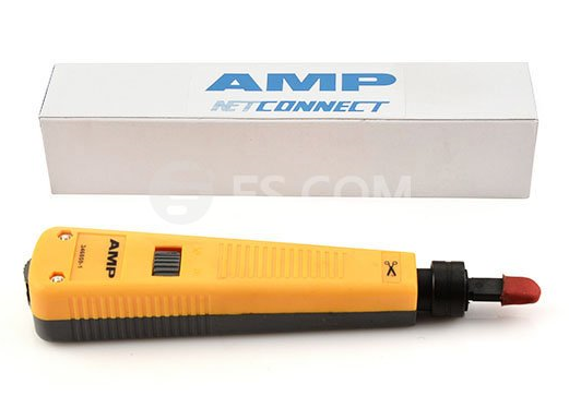
Typical on the market there are three different punch down tools available, including standard impact tool, universal automatic impact tool and corrosion resistant termination tool. Most punch down tools are of the impact type, consisting of a handle, an internal spring mechanism, and a removable slotted blade. They typically are 6-8 inches long with a blade at one end. The top and bottom of the tool are usually different colors to help users identify which side is used to cut the wire. Most models have a changeable blade and a pressure adjustment screw or knob.

The dimensions of the punch down tool are not standardized. Some tools measure 5.35 in x 1.06 in x 1.06 in and weigh 4.69 oz. Others have dimensions of 5.25 in x 1.26 in x 1.26 in, 7.00 in x 2.02 in x 2.02 in and so on. Their weights also vary. Whatever the dimensions of the punch down tool are, usage is the same.

How to Use a Punch Down Tool?
  • Prepare to punch down a wire Standing in front of the connection block, hold the punch down tool in one hand, with the cutting blade facing down. Hold the wire in your other hand and loop it through the selected connection block terminal.
  • Punch down the wire Holding the end of the wire firmly, place the blade of the punch down on the selected connection terminal and push forward until you reach the bottom of the terminal. Continuing to hold the end of the wire, punch the tool firmly with a straight-forward motion. If done correctly, this action should connect the wire to the terminal and cleanly cut off any excess.
  • Check your connection Make sure your connection is secure and there is no loose or broken wire left in the connection block. Tug on the wire to verify that it is securely fastened and connected to the correct terminal.
Conclusion

There are many types of punch down tools available and have different features. The good ones will have reversible blades. It is also important for the blade to fit in properly. The tool must also be robust. FS.COM supplies 110 punch down tool, Krone punch down tool and many other fiber optic tester and tools with competitive price.


How to Choose the Right Fiber Patch Panel?

2016-10-19 11:25:59 | Fiber Patch P

Fiber patch panel, also known as fiber enclosure, is deployed for better cable management and cable protection in data centers. Fiber patch panel terminates the fiber optic cable and provides access to the cables’ individual fibers for cross connection, which makes it easier for technicians to do the cabling work. Since there are various types of fiber patch panels in the market, choosing the right one for your network is not as easy as you think.

Loaded vs. Unloaded

Before choosing fiber patch panels, you should keep in mind that fiber optic enclosures have loaded and unloaded version. Loaded patch panel is pre-installed with adapter panels or cassettes while unloaded patch panel is empty with nothing inside. Typically, LC and MTP connectors are widely used in loaded patch panels. But these connectors in loaded panels are often permanently mounted, so if a port gets damaged it’s dead forever. Unloaded patch panel, on the contrary, is more flexible that can let you swap out defective ports at will. But extra assemblies are demanded to be purchased and installed by yourself.

loaded-unloaded patch panel

Patch Panel Rack Size

Fiber patch panel is usually measured by rack unit. A rack unit is used to describe the height of electronic equipment designed to mount in a 19-inch wide rack or a 23-inch wide rack. The height of rack-mounted equipment is frequently described as a number with U or RU. 1U refers to one rack unit, 2U refers to two rack units and so on. 2RU and 4RU are often used for high-density installations. So according to your application, the related rack size should also be adjusted.

Port Density

Port density is also an important part to be considered when purchasing fiber patch panels. As for normal patch panel, 1RU is able to carry 48 ports. If high-density patch panel is required, 1RU can support 96 ports. Moreover, 144 ports in 1RU is also available with ultra density patch panels. Since high-density has been frequently applied to the data centers, patch panels with higher port density becomes the future trend.

port-density

Migration to High-Density Patch Panels

With the wide deployment of 40G and 100G high speed networks. MPO/MTP breakout patch panel may be an ideal solution for this high-density installation. Deploying high-density patch panels has many advantages. It simplifies the cabling deployment by running a short fiber patch cable from your SAN or network switch up to the fiber patch panel. Much space can also be saved in data centers by mounting more cables into a smaller space. Installation is easier since no tools are required to install cassettes in the patch panels, and push-pull tabs are used to ease the difficulty of cable connections in the patch panels.

Conclusion

To organized and protect cables to ensure a stable network, fiber patch panel is definitely the perfect solution. When choosing fiber patch panels, you’re supposed to consider from the aspects of loaded or unloaded types, rack size, port density, etc. Besides, the high-density patch panel is a cost-effective solution that overcomes the cabling congestion in high bandwidth networking.


High-density QSFP+ SR4 Transceiver Cabling Methods

2016-10-18 10:19:28 | 40 Gigabit Ethernet

With the increasing demand for higher speed in fiber optic communications, 40G network is widely deployed in today’s backbone transmission network. 40G QSFP+ SR4 transceivers, for short reach applications, can support distance of up to 150 m over OM4 multimode optical fiber. Inserted in switch, QSFP+ SR4 module utilizes a MTP/MPO interface for dual way transmission.

There are a lot of methods to connect QSFP+ SR4 transceivers to other devices by using different connectivity products. Besides, the cabling for 40G is relatively more difficult than that of 10G network, which requires more cables and space. Here are several high density QSFP+ SR4 transceiver cabling methods.

40gb QSFP+

QSFP+ SR4 40G to 40G Applications

40G to 40G transmission is needed in a 40G fiber optic network. The following picture simply illustrates how 40G to 40G multimode transmission is being achieved by QSFP+ SR4 transceivers. Two QSFP+ SR4 modules interconnected with a MTP trunk cable are separately inserted into two switches. Thus two switches are linked successfully.

40G Cabling

Of course, there are also other ways to achieve this connection. The more devices you use, the more complex it is to achieve connections because cable counts increase. As shown in the following figure, a 48-port 1U rack mount MTP fiber patch enclosure is used. Four 12-port MTP fiber adapter panels can be deployed in this standard 1U rack mount enclosure. With the help of this 48-port MTP fiber enclosure, cable management for 40G connections could be easier.

40G high-density cabling

QSFP+ SR4 40G to 10G Applications

QSFP+ SR4 is a parallel fiber optic transceiver which uses four fibers for transmitting and four fibers for receiving at the same time. The 40G fiber optic signal can be separated into four 10G signals to meet the 40G to 10G transferring requirements. The fiber optic cable count will be increased at the 10G distribution end. Usually a breakout MTP-8LC harness cable is used. For better cable management, a 1U 96-fiber enclosure is recommended, which includes four HD MTP cassettes transferring MTP front the 40G end to LC at the 10G end. Four 10G-SR SFP+ modules, inserted in 10G switch/ports, can be connected to the corresponding LC ports on fiber optic enclosures to achieve the duplex transmission between 40G and 10G.

For higher cabling density, the above mentioned 48-port 1U rack mount MTP fiber patch enclosure is still being recommended, which can provide high density 40G MTP cabling environment. And additional MTP-8LC harness cables should be used for transferring signals between 40G and 10G.

Conclusion

Through the above analysis we can see that, QSFP+ SR4 transceivers can meet various cabling applications with different fiber products. Apart from the above-mentioned methods, there are also others way to build connections using QSFP+ SR4 modules and it will depend on the practical applications and cabling environments. All the related products for the above mentioned methods can be found in FS.COM.


Common Types of Fiber Optic Splitters

2016-10-14 16:42:18 | FTTx & Opt...

An fiber optic splitter is an essential component used in an FTTH PON where a single optical input is split into multiple output. This enables the deployment a Point to Multi Point (P2MP) physical fiber network with a single OLT port serving multiple ONTs. The most common split ratios are 1:2, 1:4, 1:8, 1:16 and 1:32. Although other split ratios are available, they are usually custom made and commands a premium. Fiber optic splitters enable a signal on an optical fiber to be distributed among two or more fibers. As a basic example, the diagram below shows how light in a single input fiber can split between four individual fibers (1x4):

1x4_splitter

Splitters can be built using a variety of single mode and multimode optical fibers and with most connector types for various applications. From a technology standpoint, there are two commonly used types of optical splitters:

  • Fused Biconic Tapered (FBT)
  • Planar Lightwave Circuit (PLC)

As with most technology, each type has both advantages and disadvantages when deploying them in a passive optical network.

Fused Biconic Tapered (FBT) Coupler Splitters

FBT is the traditional technology in which two fibers are placed closely together and fused together by applying heat while the assembly is being elongated and tapered. A signal source is used to determine the point at which the desired coupling ratio has been met, which then stops the process.

As this technology has been developed over time, the quality of FBT splitters is very good and they can be deployed in a cost-effective manner. FBT splitters are widely accepted and used in passive networks, especially for instances where the split configuration is smaller (1x2, 1x4, etc).

A drawback of this technology occurs when larger split configurations (1x16, 1x32, 1x64, etc) are required. FBT technology is limited in the number of quality splits that can be achieved in a single instance, so several must be spliced together when a larger split configuration is required. As a result, the physical size increases due to multiple splitters, along with the excess loss from the splices. Thus, for these instances, PLC splitters are more ideal as we will discuss in the next section.

Planar Lightwave Circuit (PLC) Splitters

PLC (Planar Lightwave Circuit) Splitters are Single Mode Splitters with an even split ratio from one input fiber to multiple output fibers. Available split counts are: 1x4, 1x8, 1x16, and 1x32. PLC Splitters are availble with 900µm loose tube singlemode fiber and terminated or unterminated as per your needs. Unconnectorized PLC splitters come with no connectors for easy splicing or connectorization. Connectorized PLC splitters are available with your choice of Fiber Optic Connectors: LC/UPC, LC/APC, SC/UPC, SC/APC, FC/UPC, FC/APC, and ST/UPC.

Among the many miniature parts which makes up a passive optical PLC splitter, there are three main components which are the fiber array for the input and output, and the chip. The design and assembly of these three component is the key to produce a high quality PLC splitter.

PLC splitter

A more recent technology, PLC splitters offer a better solution for applications where larger split configurations are required. To achieve this, waveguides are fabricated using lithography onto a silica glass substrate, which allows for routing specific percentages of light. As a result, PLC splitters offer very accurate and even splits with minimal loss in an efficient package.

With the rapid growth of FTTx worldwide, the requirement for larger split configurations (1x32, 1x64, etc) in these networks has also grown in order to serve mass subscribers. Due to the performance benefits and overall low cost to deploy, PLC splitters are now the ideal solutions for these types of applications.


Three Steps to Build a Copper Network at Home

2016-10-12 15:59:39 | Copper Net...

Wireless access is popular at home today, however, most of our home devices are with copper based interfaces and they can work better through a wired connection to the broadband. Thus, copper based networks are still very important in our daily life.

Building a copper network at home is easier than building a fiber network. Before deploy the copper home network, you should firstly understand what you want from this copper home network. Of course, easier access to broadband and WiFi is the most basic requirement. Also remember to determine the port number and expectation of the network performance, which is closely related to the product selection and cost of your network. Here are three steps to follow when building a copper network at home.

copper network

Step One: Introduce Service Provider Distribution Cable to Your Home

Now most of the broadband service provider will install a distribution point near or inside a building. As shown in the above picture, copper network cables or fiber optic cables are deployed inside a building to bring services to every houses inside this building. For some old buildings, the cables between the end users and distribution point are still copper based. For many new buildings, these cables are usually fiber optic based. Just add an ONU (Optical Network Unit), you can change these optical signals into electrical signals and distribute signals to different ports and home devices. If your apartment is a small one, you can just use one ONU or router in the whole home network.

There are a variety of ONUs and routers which can support WiFi and satisfy various port requirements. For example, the following picture shows the application of a typical ONU that can meet the requirement of most apartments. This ONU has a SC optical interface to be connected with the service provider’s entry fiber optic cable. Except two voice ports and four LAN ports, this ONU provides WiFi function.

Step Two: Wiring the Whole House

Wiring the whole house is very important for a home network with good broadband access. It is known that most home devices have better performance via a wired connection compared with being connected to WiFi. So during this process, you should device the port number you should leave in your house and how many devices should be connected to the network. Now there are a variety of home devices can be connected to a home network for better and smarter performance, which is also called smart home. Devices like air condition, light control and televisions can all be connected to the home network. Thus, copper network cable for signal transmission should have good and reliable performance. Cat6 and Cat7, two types of high performance Category copper cable, which can meet the requirement for both now and future, are strongly recommended.

wire home

The above picture shows the copper cabling for an apartment. The bedroom, living room, office and dining room of this house is all connected to broadband via copper network cable. In addition, each room is connected to voice cable ensuring that the house owner would not miss phone calls in most part of the house.

Step Three: Terminate Copper Cables and Connect Them to Home Devices

For the sake of security and reliability, the copper network cables should be terminated at wall plate ports. And a length of RJ45 copper network patch cable should be used to connect the port with target device as shown in the following picture.

copper home network

FS.COM Copper Networking Solutions

Good broadband access is very important to deploy a copper based home network. However, select the right cabling product is also important. FS.COM provides a wide range of copper network products for not only home network use but also for data center use, including Cat5, Cat5e, Cat6 and Cat7 cable, patch panels and cable jackets and plugs. All these products are available in different colors and can be customized in FS.COM.