Fiber Optic Tech

Sharing various fiber optic news, inforamtion, topics, etc.

Installation Guide for RJ45 Modular Jack on CAT5e Shielded Cable

2017-02-16 10:42:39 | Copper Net...

RJ45 modular jack is used for mounting optical connectors into the wall plate or patch panel for network wiring installs. There are numerous requests for wiring diagrams or general information on how to punch down or terminate keystone jacks (Cat5e / Cat6) after running your telecom network's cross-connect cabling. Building a patch cable involves installing RJ45 plug connectors on each end of a stranded cable. Here we describe the process of installing the RJ45 connectors.

Attaching cable connectors involves the use of very sharp knives for stripping cable insulation as well as crimping tools that can be dangerous to operate. Many crimping tools incorporate a ratchet mechanism that, once engaged, prevents the tool from being opened until it has first closed completely. Anything caught in the crimping tool, including your fingers, will be crushed.

Step1

Cut cable to needed length. Remove the outer jacket of the cable using the Cable Prep Tool. Place the tool approximately 1.5” from end of the cable. Rotate tool at least twice around the cable, both clockwise and counter-clockwise. That will score the jacket allowing you to remove it without damaging the conductors inside the jacket.

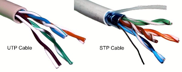
Carefully strip away a few inches of the outer insulation from the twisted-pair cable, revealing the individually insulated twisted-pair conductors inside. Each twisted-pair conductor consists of a set of thin stranded wire surrounded by insulation. Do not cut the insulation of the twisted-pair conductors.

Step2

Orient the conductors according to the colors of the insulation. Pull the wire braid back over the outer jacket. Trim off the clear plastic jacket.

Step3

Straighten out the twisted-pair conductors, arrange them and cut the conductors to a length about 12mm. Leave the insulation in place on the individual twisted-pair conductors. Make sure that the conductors are all cut to the same length, providing a square end to the cut. Untwist and separate all of the conductor pairs.

TIP: Use the jacket that was just removed and feed each conductor down the jacket to untwist it. Bonded twisted pair cable can be separated using a 1797B cable separator.

Step4

Use the outer edge of the cable scissors to straighten conductors. Using gentle pressure (to avoid damage to the conductors), put each conductor between thumb and edge of cutter and pull up from outer jacket to end of the conductor.

Step5

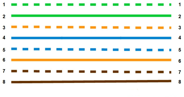
Arrange the conductors in the order shown: 1. White/Orange 2. Orange 3. White/Green 4. Blue 5. White/Blue 6. Green 7. White/Brown 8. Brown

Step6

Bring the sorted conductors together, holding tightly between the thumb and forefinger. Recheck to ensure the wiring sequence is correct. Cut the wires at a 90º angle about 1/2” from the end of the jacket.

Step7

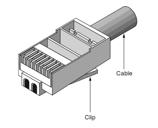
Insert the conductors into the plug. Hold the plug with the copper contacts facing up and the locking tab facing down. In this position, the orange/white conductor should be the first conductor on the left. Insert the conductors into the plug. Make sure the drain wire is wrapped around the jacket underneath the back of the plug prior to crimping in order to complete the ground.

Step8

Crimping the plug using the cable crimping tool. Place the plug into the crimp tool and squeeze handles tightly. The copper splicing tabs on the plug will pierce into each of the eight conductors. The locking tab will cinch onto the outer jacket of the cable.

Step9

Remove plug from tool. Check the conductor sequence and ensure outer jacket is inside the plug and secured by the locking tab. Trim excess drain wire just below entry into plug.

Step10

Repeat steps for other end of cable. Then use a cable tester to ensure proper installation and wiring of plugs.


Shielded vs. Unshielded Twisted-Pair Cable

2017-02-10 14:14:19 | Copper Net...

As we all know, the advantages and disadvantages of shielded and unshielded twisted-pair cable are under debate for a long time. Advocates of STP cable, which includes screened twisted-pair and foil twisted-pair cables, claim that it is superior to UTP cable. Shielded versus unshielded twisted-pair cable, which is the winner? This post will give you the answer.

STP and UTP cable differ in design and manufacture. But their purpose should be the same--to provide reliable connectivity of electronic equipment. In theory, both types of cable should do this equally well. The true test comes when you look at how each of these cable types performs that task within its respective end-to-end system.

Shielded vs. Unshielded Twisted-Pair Cable

Shielded Twisted-Pair Cable

Shielded twisted-pair cable encases the signal-carrying wires in a conducting shield as a means of reducing the potential for electromagnetic interference. How effective the shielding is depends on the material used for the shield--its thickness and frequency, the type of electromagnetic noise field, the distance from the noise source to the shield, any shield discontinuity and the grounding practices. Also, crosstalk and signal noise can increase if the effects of the shield are not compensated for.

Some STP cables, for example, use a thick braided shield that makes a cable heavier, thicker and more difficult to install than its UTP counterpart. Other STP cables use only a thin outer foil shield. These cables, known as screened twisted-pair cables or foil twisted-pair cables, are thinner and less expensive than braided STP cable; however, they are not any easier to install. Unless the minimum bend radius and maximum pulling tension are rigidly observed when these cables are installed, the shield can be torn.

Unshielded Twisted-Pair Cable

Unshielded twisted-pair cable does not rely on physical shielding to block interference. It relies instead on balancing and filtering techniques using media filters, baluns or both. Noise is induced equally on two conductors and is canceled out at the receiver. With properly designed, manufactured and installed UTP cable (like CAT6 UTP cable), the network is easier to maintain than one in an STP cable plant, with its shielding continuity and grounding issues.

UTP cable has evolved during the years, and different types are available for different needs. Basic telephone cable, also known as direct-inside wire, is still available. Improvements over the years--variations in the twists or in individual wire sheaths or overall cable jackets--have led to the development of Cat3 cable that is compliant with the Electronic Industries Association/ Telecommunications Industry Association-568 standard for transmission rates up to 16 megahertz. Cat 4 UTP cable is specified for signal bandwidths to 20 MHz, and Cat5e UTP cable for specifications to 100 MHz--and possibly higher.

Shielded vs. Unshielded Twisted-Pair Cable

Since UTP cable is lightweight, thin and flexible, as well as versatile, reliable and inexpensive, millions of nodes have been, and continue to be, wired with this cabling medium. This is especially true for high-data-rate applications. For best performance, this UTP cable should be used as part of a well-engineered structured cabling system.

If STP cable is combined with improperly shielded connectors, connecting hardware or outlets, or if the foil shield itself is damaged, overall signal quality will be degraded. This, in turn, can result in degraded emission and immunity performance. Therefore, for a shielded cabling system to totally reduce interference, every component within that system must be fully and seamlessly shielded, as well as properly installed and maintained.

An STP cabling system also requires good grounding and earthing practices because of the presence of the shield. An improperly grounded system can be a primary source of emissions and interference. Whether this ground is at one end or both ends of the cable run depends on the frequency at which a given application is running. For high-frequency signals, an STP cabling system must be grounded, at minimum, at both ends of the cable run, and it must be continuous. A shield grounded at only one end is not effective against magnetic-field interference.

The length of the ground conductor itself can also cause problems. If it is too long, it no longer acts as a ground. Therefore, because specific grounding requirements depend on the application, a general grounding policy that ensures the best results for an STP cabling system is not possible.

UTP cabling doesn’t have this problem. While an STP cabling system is dependent on such factors as physical continuity of the cable shield or installation with adequately shielded and grounded components, a UTP cabling system inherently has fewer potential trouble spots and is much easier to install.


Demystifying Twisted-Pair Cable Connector Types

2017-02-06 12:26:08 | Copper Net...

Have you ever wired a cable directly into a piece of hardware? Some equipment in the past years provided terminals or termination blocks so that cable could be wired directly into a direct component. At the ends of the cables you install, something must provide access and transition for attachment to system electronics. Thus, you need connectors.

Connectors usually have a male component and a female one, except in the case of hermaphroditic connectors such as the IBM data connector. Jacks and plug are usually systematically shaped, but sometimes they are keyed, which means that they have a unique, asymmetric shape or some system of pins, tabs and slots that ensure that the plug can be inserted only one way in the jack. This article covers three types of connectors you may encounter when working with structured cabling system.

Many people in the cabling business use twisted-pair connectors more than any other type of connector. The connectors included the modular RJ types of jacks and plugs and the hermaphroditic connector employed by IBM that is used with shielded twisted-pair cabling (ie. cat6 shielded cable). What is equally important as the cable connector is the connector used with patch panels, punch-down blocks, and wall plates; this connector is called an IDC (insulation displacemeny connector).

Patch-Panel Terminations

Most unshielded twisted-pair (UTP) and screened twisted-pair (ScTP) cable installations use patch panels and, consequently, 110-style termination blocks. The 110-block contains rows of specially designed slots in which the cables are terminated using a punch-down tool.

Solid vs. Stranded Conductor Cables UTP and ScTP cables have either solid copper conductors or conductors made of several tiny strands of copper. Solid conductors are very stable geometrically and therefore electrically superior, but they will break if flexed very often. Stranded conductors are very flexible and resistant to bend-fatigue breaks, but their cross-sectional geometry changes as they are moved, and this can contribute to electrical anomalies. Stranded cables also have a higher attenuation than solid-conductor cables.

The differences in conductors mean a difference in IDC types. You have to be careful when purchasing plugs, wall plates, and patch panels because they won’t work interchangeably with solid- and stranded-core cables because the blade designs are different.

Modular Jacks and Plugs

Twisted-pair cables are most commonly available as UTP, but occasionally, a customer or environmental circumstances may require that ScTP cable be installed. In an ScTP cable, the individual twisted pairs are not shielded, but all the pairs collectively have a thin shielded around the shielded of foil around them. Both UTP and ScTP cables use modular jacks and plugs. For decades, modular jacks have been commonplace in the home for telephone wiring.

Modular connectors come in four-, six-, and eight-position configurations. The number of positions defines the width of the connector. However, many times not all of the positions have metal contacts installed. Make sure that the connectors you purchase are properly populated with contacts for your application. Note the metal shield around the jack; it is designed to help reduce both EMI emissions and interference from outside sources, but it must be connected properly to the cable shield to be effective. The following figure shows an eight-position modular plug for UTP cable.

modular plug

Shielded Twisted-Pair Connectors

Shielded twisted-pair connectors go with the shielded twisted-pair cable which encases the signal-carrying wires in a conducting shield as a means of reducing the potential for electromagnetic interference. How effective the shielding is depends on the material used for the shield--its thickness and frequency, the type of electromagnetic noise field, the distance from the noise source to the shield, any shield discontinuity and the grounding practices. Please note that the crosstalk and signal noise can increase if the effects of the shield are not compensated for.


Straight-Through vs. Crossover Ethernet Cables

2017-02-04 09:56:29 | Copper Net...

Ethernet cables or networks cables are used for data transmission between devices on a network. They consist of a copper cable with 4 pairs of wires and connected by RJ45 connectors on each end of the cable. Most Ethernet cables in use today are either Cat5e and Cat6 which offer higher data transfer rates than the older types such as Cat5 and Cat4. Although various types of Ethernet cables look the same, the internal wiring distinguishes. Ethernet cables can come in two different wiring applications: straight-through and crossover, each of them with different wire arrangement in the cable for serving different purposes.

Straight-Through Ethernet Cables

Straight-through cable is the most common type and is used to connect different type of devices. This type of cable is easy to find in stores and can be used to: 1)Connect a computer to a switch/hub's normal port.

2)Connect a computer to a cable/DSL modem's LAN port.

3) Connect a router's WAN port to a cable/DSL modem's LAN port.

4) Connect a router's LAN port to a switch/hub's uplink port. (normally used for expanding network)

5) Connect 2 switches/hubs with one of the switch/hub using an uplink port and the other one using normal port.

If you need to check how straight-through cable looks like, it's easy. Both side (side A and side B) of cable have wire arrangement with same color. For example, Cat5e UTP cable usually uses only four wires when sending and receiving information on the network. The four wires, which are used, are wires 1, 2, 3, and 6. When you configure the wire for the same pin at either end of the cable, this is known as a straight-through cable.

Straight-Through Ethernet Cables

Crossover Ethernet Cables

Crossover cables are usually used to connect the same type of devices and may be a little harder to find since they aren’t used nearly as much as straight-through cables. A crossover cable can be used to: 1) Connect 2 computers directly.

2) Connect a router's LAN port to a switch/hub's normal port. (normally used for expanding network).

3) Connect 2 switches/hubs by using normal port in both switches/hubs.

Compared with straight-through Ethernet cables, the internal wiring of crossover cables reverses the transmit and receive signals. That is to say, the two end of the crossover Ethernet cable are wired differently. And the reversed color-coded wires can be seen through the RJ-45 connectors at each end of the cable.

Crossover Ethernet Cables

Identifying Straight-Through and Crossover Cables

Whether they are straight-through or crossover cables, all Ethernet cables essentially look the same. When dealing with the inevitable pile of unlabeled cables that forms in every home, this can make dealing with them tricky. Fortunately, you can quickly identify crossover and straight cables if you know what to look for.

When determining if an Ethernet cable is a straight or crossover cable, examine the connectors. Observe the pin configuration carefully. The pins are color coded, so you should have no trouble doing this. If the pins are configured in the same way, you are looking at a straight cable. If not, it is a crossover cable.

Conclusion

Nowadays, the need for crossover cables has been eliminated with more modern equipment. Gigabit Ethernet was created with a widely used option called Auto-MDIX (automatic medium-dependent interface crossover). This technology detects whether you need a crossover cable or a straight-through cable, and it automatically configures the network interface card accordingly, which means that crossover function would be enabled automatically when it's needed.


Introduction to Cat6 Ethernet Cables

2017-01-26 14:50:54 | Copper Net...
The Emergence of Cat6 Cable

Category 6 (CAT6) is an Ethernet cable standard defined by the Electronic Industries Association and Telecommunications Industry Association (commonly known as EIA/TIA). CAT6 is the sixth generation of twisted pair Ethernet cabling. Cat6 increases the bandwidth of the Cat5/5e from 100MHz to 250 MHz and allows for better signal to noise ratio with minimal loss which ensures faster and reliable networks. Cat6 also has many benefits compared to the Cat5/5e such as backwards compatibility, ease of installation, high performance, faster speeds, and higher capacity.

How CAT6 Cable Works

Category 6 was designed to support Gigabit Ethernet data rates (1 gigabit per second - Gbps). It additionally can support 10 Gigabit Ethernet connections over a limited distance (technically, 50 meters or 164 feet for a single cable).

CAT6 cable contains four pairs of copper wire and utilizes all of these pairs for signaling in order to obtain the higher level of performance.

Other basic facts about CAT6 cables
  • Ends of a CAT6 cable use the same RJ-45 standard connector as previous generations of Ethernet cables.
  • Printing along the length of the cable sheath identifies it as "CAT6".
  • An enhanced version of CAT6 called CAT6a supports up to 10 Gbps speeds.
CAT6 vs. CAT6A

The Category 6 Augmented (CAT6A) cable standard was created to further improve on the performance of CAT6 for Ethernet cables. Using CAT6A enables 10 Gigabit Ethernet data rates over a single cable run up to 100 meters (328 feet). twice as far as CAT6, which supports 10 Gigabit Ethernet also, but only over distances up to 50 meters (164 feet). In return for the higher performance, CAT6A cables tend to cost noticeably more than their CAT6 counterparts, and they are slightly thicker (but still use standard RJ-45 connectors).

CAT6 vs. CAT5e

The history of cable design for Ethernet networks resulted in two separate efforts to improve on the previous generation Category 5 (CAT5) cable standard. One eventually became CAT6. The other, called Category 5 enhanced (CAT5e), was standardized earlier. CAT5e lacks some of the technical improvements that went into CAT6 but also supports Gigabit Ethernet installations, and at a lower cost.

Like CAT6, CAT5e utilizes a four wire pair signaling scheme to achieve the necessary data rates. (In contrast, CAT5 cables contain four wire pairs but keep two of the pairs dormant.)

Because it became available in the market sooner and offered "good enough" performance for Gigabit Ethernet at a more affordable price point, CAT5e became a very popular choice for wired Ethernet installations. This plus the relatively slow transition of the industry to 10 Gigabit Ethernet has significantly slowed the adoption of CAT6.

Limitations of CAT6

As with all other types of twisted pair EIA/TIA cabling, individual CAT6 cable runs are limited to a maximum recommended length of 100 meters (328 feet) for their nominal connection speeds (Gigabit Ethernet). As mentioned above, CAT6 supports 10 Gigabit Ethernet connections also but not at this full distance. Besides, CAT6 cable price is a little higher than that of CAT5e cable. So before choosing it, you’d better measure whether it is worth the extra cost.