goo blog サービス終了のお知らせ 

Fiber Optic Tech

Sharing various fiber optic news, inforamtion, topics, etc.

3rd-party Optical Transceivers Innovation for Your Bottom Line

2016-11-28 14:49:35 | Fiber Optic Transcei

With the lightning fast changes of today’s technology, staying on the cutting edge can be a great challenge. A company’s data center and infrastructures have become one of the most strategic assets it owns, and conventional wisdom says that in order to support topline business growth, companies must spend money to make money.

However, this axiom is not true when it comes to optical transceivers. Using 3rd-party optics instead of name brand optics from the Original Equipment Manufacturer (OEM) is a smart and innovative way to embrace changes in the dynamic networking and data center hardware markets, while protecting your bottom line by not paying exorbitant prices. This article will briefly explain the value and advantages that 3rd-party optical transceivers provide.

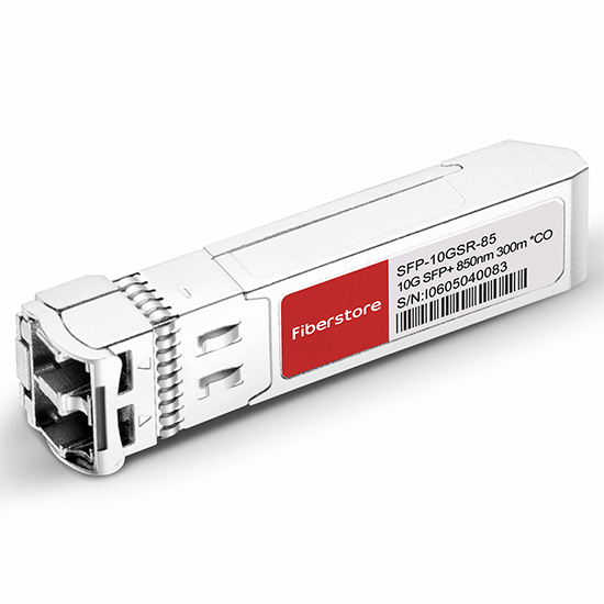
SFP transceiver

Sourcing and Price

Optics that you buy directly from an OEM are not necessarily original. OEMs actually buy their optics from master suppliers who code and label the products for them. An OEM’s price to the customer will factor in the costs of testing and validation, but the majority of what you pay for goes into the OEM’s pocket as pure profit. Third party optics providers source their products from the same (or equivalent) suppliers as used by OEMs. There are numerous third party optics resellers, and they may not all use the same testing procedures, but most have nearly 100% success in compatibility with the corresponding OEM equipment. The real difference between OEM and third party is that third party optics providers do not mark up the product as much as OEMs – which translates into significantly better pricing for the customer.

Quality and Reliability

You can find third party optics for virtually any product or platform. While Cisco comprises a large number of the compatible optics in the networking space, every product that requires a copper or fiber optic connection to another device will need an optic of one type or another. It is very important to ask your third party optics supplier about which OEMs and product lines they specialize in, and to inquire about detailed information on their testing procedures.

You’ll want to make sure that any third party optics you buy are compatible with the operating systems from different OEMs and the latest corresponding software releases. A good way to glean this information from your third party optics supplier is to ask for a list of the equipment in their test bed. This will also allow you to request testing logs and compatibility reporting as needed.

Warranty and Support

Last but most importantly, the best third party optics providers will stand behind their product after you’ve bought them. Because many third party optics providers are highly focused and specialize in the optical transceiver market, they will offer a lifetime warranty on their products. It is inevitable that at one point or another, even with name brand OEM optics, a few optics that you buy will fail. Failures occur most frequently when the software in networking and data center hardware is updated, causing incompatibility with existing optics. Ideal third party optics providers will be able to troubleshoot and replace the optic for you quickly and at minimal to no cost.

Buying 3rd-party optical transceivers may not be as attractive as the products and technologies they support, yet they can enable an organization to maximize the budget it has for IT projects. Finally, while identifying sources with the lowest prices is a common goal, smart customers should look at third party optics suppliers holistically, and factor things like breadth of products supported, compatibility and testing processes, support offerings, and reputation into their buying decisions.


Getting to Know SONET/SDH SFP+ Transceivers

2016-11-25 14:13:34 | Fiber Optical Transc

Plesiochronous Digital Hierarchy (PDH) system was the earliest stand used to transport phone calls and data over the same fiber. With the increasing demand of phone calls and data traffic, SONET/SDH are then introduced to replace PDH system to transport the data without synchronization problems. As you can see, SONET/SDH SFP+ transceivers have been widely used in the market. This post will give a brief analysis on SONET/SDH SFP+ transceivers.

10gbase SR

SONET/SDH Interfaces Overview

SONET (Synchronous Optical Networking) and SDH (Synchronous Digital Hierarchy) are multiplexing protocols that transfer multiple digital bit streams over optical fiber with lasers or light-emitting diodes (LEDs). SONET and SDH are widely used methods today for very high speed transmission of voice and data signals across the numerous world-wide fiber-optic networks. SONET is the standard used in the United States and Canada, and SDH in the rest of the world. The two are largely equivalent. Although the SONET standards were developed before SDH, it is considered a variation of SDH because of SDH’s greater worldwide market penetration.

We often find SONET/SDH SFP transceiver like Cisco OC-3/STM-1 LR-1 SFP 1310nm 40km IND DOM. What does OC-3/STM-1 mean? OC-3c (Synchronous Transport Signal 3, concatenated) is the basic unit of SONET. Depending on the system, OC-3 is also known as STS-3 (when the signal is carried electrically). STM-1 (Synchronous Transport Module, level 1) is the basic unit of framing in SDH, which operates 155.52 Mbit/s. OC-3c and STM-1 have the same high-level functionality, frame size, and bit-rate.

SONET/SDH and 10 Gigabit Ethernet

10 Gigabit Ethernet (10GbE) means the Ethernet network runs at 10 Gigabit per second. The 10 Gigabit Ethernet defines two PHY (Physical Layer) types: a local area variant (LAN PHY) with a line rate of 10.3125 Gbit/s, and a wide area variant (WAN PHY) with the same line rate as OC-192/STM-64 (9,953,280 Kbit/s).

10GbE provided the potential for an Ethernet solution aligned with the data rate of OC-192 backbone. It’s the first time in Ethernet history that no additional speed matching equipment would be required to link with the WAN. A seamless end-to-end Ethernet network can be built with less money. But the question is how to balance the compatibility with the installed base of OC-192 equipment while still meeting the economic feasibility criteria of the P802.3ae Task Force in defining the 10GE WAN PHY. To solve this problem, an OC-192 frame format is provided to support only the SONET overhead features required for fault isolation. This simplification avoids unnecessary functions and cost.

In order to make sure that WAN PHY optics would benefit from the high volumes and low cost of Ethernet, the serial 1310 nm and 1550 nm transceiver modules were kept the same as the LAN PHY. Since the 1310 nm and 1550 nm transceiver modules are designed for up to 10km and 40 km links respectively, they will inter-operate with OC-192 transceiver modules for 1310 nm and 1550 nm over intermediate reach, respectively.

FS.COM SONET/SDH SFP+

FS.COM supplies OC-192/STM-64 SFP+ for short reach (SR-1, VSR) , intermediate reach (IR-2) and long reach (LR-2) applications. These SFP+ modules are compatible with the SONET/SDH and ATM standards. For more details, please visit the website at fs.com.


How Much Do You Know About OADM

2016-11-23 16:38:09 | WDM

The OADM, short for optical add drop multiplexer, is one of the key components for dense wavelength division multiplexing (DWDM) and ultra wide wavelength division multiplexing (UW-WDM) optical networks. OADM technology is used to cost effectively access part of the bandwidth in the optical domain being passed through the in-line amplifiers with minimum amount of electronics.

An OADM can be considered as a specific type of optical cross-connect, widely used in wavelength division multiplexing (WDM) systems for multiplexing and routing fiber optic signals. They selectively add and drop individual or sets of wavelength channels from a dense wavelength division multiplexing (DWDM) multi-channel stream. OADMs are used to cost effectively access part of the bandwidth in the optical domain being passed through the in-line amplifiers with the minimum amount of electronics.

OADMs have passive and active modes depending on the wavelength. In passive OADM, the add and drop wavelengths are fixed beforehand while in dynamic mode, OADM can be set to any wavelength after installation. Passive OADM uses WDM filter, fiber gratings, and planar waveguides in networks with WDM systems. Dynamic OADM can select any wavelength by provisioning on demand without changing its physical configuration. It is also less expensive and more flexible than passive OADM. Dynamic OADM is separated into two generations.

A typical OADM consists of three stages: an optical demultiplexer, an optical multiplexer, and between them a method of reconfiguring the paths between the optical demultiplexer, the optical multiplexer and a set of ports for adding and dropping signals. The MUX multiplexes the wavelength channels that are to continue on from DEMUX ports with those from the add ports, onto a single output fiber, while the DEMUX separates wavelengths in an input fiber onto ports. The reconfiguration can be achieved by a fiber patch panel or by optical switches which direct the wavelengths to the MUX or to drop ports. All the light paths that directly pass an OADM are termed cut-through lightpaths, while those that are added or dropped at the OADM node are termed added/dropped lightpaths.

OADM works as follows: the WDM signals from line containing N wavelength channels enter the OADM "Main Input" side, depending on your business needs, from N wavelength channel, selectively from the road-side (Drop) required by the output wavelength channel, accordingly from the road-end (Add) enter the desired wavelength channel. Regardless of other local wavelength channel directly through the OADM, and routing wavelength channels multiplexed together, from the output terminals of the circuit of OADM (Main Output) output. The following picture shows the basic operation of an OADM.

basic-operation-of-oadm

Physically, there are several ways to realize an OADM. There are a variety of demultiplexer and multiplexer technologies including thin film filters, fiber Bragg gratings with optical circulators, free space grating devices and integrated planar arrayed waveguide gratings. The switching or reconfiguration functions range from the manual fiber patch panel to a variety of switching technologies including microelectromechanical systems (MEMS), liquid crystal and thermo-optic switches in planar waveguide circuits.

CWDM and DWDM OADM provide data access for intermediate network devices along a shared optical media network path. Regardless of the network topology, OADM access points allow design flexibility to communicate to locations along the fiber path. CWDM OADM provides the ability to add or drop a single wavelength or multi-wavelengths from a fully multiplexed optical signal. This permits intermediate locations between remote sites to access the common, point-to-point fiber message linking them. Wavelengths not dropped, pass-through the OADM and keep on in the direction of the remote site. Additional selected wavelengths can be added or dropped by successive OADMS as needed.

FS.COM provides a wide selection of specialized OADMs for WDM system. Custom WDM solutions are also available for applications beyond the current product designs including mixed combinations of CWDM and DWDM.


Advantages of 10GBASE-T in Migrating to 10GbE

2016-11-16 18:19:09 | 10 Gigabit Ethernet

Over the past few decades, large enterprises have been migrating data center infrastructures from 100MB Ethernet to 1/10 Gigabit Ethernet (GbE) to support more bandwidth and mission critical applications. However, many mid-market companies found themselves restricted from this migration to 10GbE technology due to cost, low port density and high power consumption. For many of these companies, the explosive growth of technologies, data and applications is severely taxing existing 1GbE infrastructures and affecting performance. So it’s high time for them to upgrade the data center to 10GbE. With many 10GbE interfaces options such as CX4, SFP+ Fiber, SFP+ Direct Attach Copper (DAC), and 10GBASE-T offered, which one is the best? This article will give you the answer.

SFP+

Shortcomings of SFP+ in 10GbE Data Center Cabling

SFP+ has been adopted on Ethernet adapters and switches and supports both copper and fiber optic cables makes it a better solution than CX4, which is the mainstream 10GbE adoption today. However, SFP+ (eg. 10gbase SR) is not backward-compatible with the twisted-pair 1GbE broadly deployed throughout the data center. SFP+ connectors and their cabling were not compatible with the RJ-45 connectors used on 1GbE networks. Enterprise customers cannot just start adding SFP+ 10GbE to an existing RJ-45 1GbE infrastructure. New switches and new cables are required, which is a big chunk of change.

Advantages of 10GBASE-T in 10GbE Data Center Cabling

10GBASE-T is backward-compatible with 1000BASE-T, it can be deployed in existing 1GbE switch infrastructures in the data centers that are cabled with CAT6, CAT6A or above cabling. As we know, 1GbE is still widely used in data center. 10GBASE-T is backwards compatible with 1GbE and thus will become the perfect choice for gradual transitioning from 1GbE deployment to 10GbE. Additional advantages include:

  • Reach Like all BASE-T implementations, 10GBASE-T works for lengths up to 100 meters giving IT managers a far-greater level of flexibility in connecting devices in the data center. With flexibility in reach, 10GBASE-T can accommodate either top of the rack, middle of row, or end of the row network topologies. This gives IT managers the most flexibility in server placement since it will work with existing structured cabling systems.
  • Power The challenge with 10GBASE-T is that even single-chip 10GBASE-T adapters consume a watt or two more than the SFP+ alternatives. More power consumption is not a good thing in the data center. However, the expected incremental costs in power over the life of a typical data center are far less than the amount of money saved from reduced cabling costs. Besides, with process improvements, chips improved from one generation to the next. The power and cost of the latest 10GBASE-T PHYs will be reduced greatly than before.
  • Reliability Another challenge with 10GBASE-T is whether it could deliver the reliability and low bit-error rate of SFP+. This skepticism can also be expressed as whether the high demands of FCoE could be met with 10GBASE-T. In fact, Cisco has announced that it had successfully qualified FCoE over 10GBASE-T and is supporting it on its newer switches that support 10GBASE-T in 2013.
  • Latency Depending on packet size, latency for 1000BASE-T ranges from sub-microsecond to over 12 microseconds. 10GBASE-T ranges from just over 2 microseconds to less than 4 microseconds, a much narrower latency range. For Ethernet packet sizes of 512B or larger, 10GBASE-T’s overall throughout offers an advantage over 1000BASE-T. Latency for 10GBASE-T is more than 3 times lower than 1000BASE-T at larger packet sizes. Only the most latent sensitive applications such as HPC or high frequency trading systems would notice any latency.
  • Cost When it comes to capital costs, copper cables offer great savings. Typically, passive copper cables are two to five times less expensive for comparable lengths of fiber. In a 1,000-node cluster, with hundreds of required cables, that can translate into the hundreds of thousands of dollars. Extending that into even larger data centers, the savings can reach into the millions. Besides, copper cables do not consume power and because their thermal design requires less cooling, there are extensive savings on operating expenditures within the data center. Hundreds of kilowatts can be saved by using copper cables versus fiber.
Conclusion

From the above analysis, we can see that 10GBASE-T breaks through important cost and cable installation barriers in 10GbE deployment as well as offering investment protection via backwards compatibility with 1GbE networks. Deployment of 10GBASE-T will simplify the networking transition by providing an easier path to migrate to 10GbE infrastructure in support of higher bandwidth needed for virtualized servers. In the future, 10GBASE-T will be the best option for 10GbE data center cabling!


Introduction to DWDM Technology

2016-11-14 15:51:48 | FTTx & Opt...

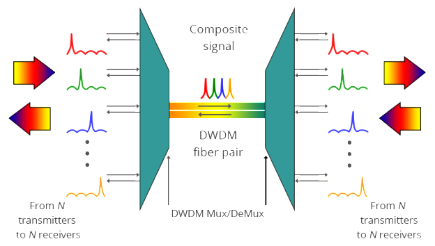
As the most popular WDM technology, DWDM (Dense wavelength-division multiplexing) revolutionized data transmission technology by increasing the capacity signal of embedded fiber. This increase means that the incoming optical signals are assigned to specific wavelengths within a designated frequency band, then multiplexed onto one fiber. By providing channel spacings of 50 GHz (0.4 nm), 100 GHz (0.8 nm) or 200 GHz (1.6 nm), several hundreds of wavelengths can be placed on a single fiber. DWDM takes advantage of the operating window of the Erbium Doped Fibre Amplifier (EDFA) to amplify the optical channels and extend the operating range of the system to over 1500 kilometers. The following picture shows the operation of a DWDM system.

bi-directional-dwdm-operation1-624x354

Components of DWDM System

A typical DWDM system is composed of transmitter, receiver, optical amplifier, transponder, DWDM multiplexer and DWDM demultiplexer. They allow DWDM system to interface with other equipment and to implement optical solutions throughout the network, complying with the ITU channel standards.

  • Optical transmitters/receivers Transmitters in DWDM systems provide the source signals which are then multiplexed. Multiple optical transmitters are used as the light sources in a DWDM system. We can also utilize a transceiver to replace transmitters and receivers to achieve the same purpose. Usually a DWDM transceiver applied in DWDM network can reach a transmission distance of up to 120km.
  • Optical amplifiers Optical amplifiers (OAs) boost the amplitude or add gain to optical signals passing on a fiber by directly stimulating the photons of the signal with extra energy. They are “in-fiber” devices. OAs amplify optical signals across a broad range of wavelengths. This is very important for DWDM system application. Erbium-doped fiber amplifiers (EDFAs) are the most commonly used type of in-fiber optical fibre.
  • Transponders Transponders are designed to convert optical signals from one incoming wavelength to another outgoing wavelength suitable for DWDM applications. Transponders are optical-electricaloptical (O-E-O) wavelength converters. Within a DWDM system, a transponder converts the client optical signal back to an electrical signal (O-E) and then performs either 2R (reamplify, reshape) or 3R (reamplify, reshape, and retime) functions. A transponder is located between a client device and a DWDM system. From left to right, the transponder receives an optical bit stream operating at one particular wavelength (1310 nm). The transponder converts the operating wavelength of the incoming bitstream to an ITU-compliant wavelength. It transmits its output into a DWDM system. On the receive side (right to left), the process is reversed. The transponder receives an ITU-compliant bit stream and converts the signals back to the wavelength used by the client device.
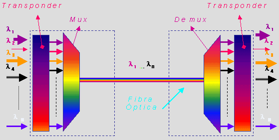
  • DWDM Multiplexers and Demultiplexers Multiple wavelengths (all within the 1550 nm band) created by multiple transmitters and operating on different fibers are combined onto one fiber by way of an optical multiplexer. The output signal of an optical multiplexer is referred to as a composite signal. At the receiving end, a demultiplexer separates all of the individual wavelengths of the composite signal out to individual fibers. The DWDM demultiplexers are capable of distinguishing each wavelength without crosstalk. The individual fibers pass the demultiplexed wavelengths to as many optical receivers. Typically, mux and demux (transmit and receive) components are contained in a single enclosure. Optical mux/demux devices can be passive. Component signals are multiplexed and demultiplexed optically, not electronically, therefore no external power source is required.

    dwdm-multiplex-and-demultiplex
Applications of DWDM

As occurs with many new technologies, the potential ways in which DWDM can be used are only beginning to be explored. Already, however, the technology has proven to be particularly well suited for several vital applications.

DWDM is ready made for long-distance telecommunications operators that use either point–to–point or ring topologies. The sudden availability of 16 new transmission channels where there used to be one dramatically improves an operator’s ability to expand capacity and simultaneously set aside backup bandwidth without installing new fiber.

This large amount of capacity is critical to the development of self-healing rings, which characterize today’s most sophisticated telecom networks. By deploying DWDM terminals, an operator can construct a 100% protected, 40 Gb/s ring, with 16 separate communication signals using only two fibers.

Conclusion

DWDM is the clear winner in the backbone. It was first deployed on long-haul routes in a time of fiber scarcity. Then the equipment savings made it the solution of choice for new long-haul routes, even when ample fiber was available. While DWDM can relieve fiber exhaust in the metropolitan area, its value in this market extends beyond this single advantage. Alternatives for capacity enhancement exist, such as pulling new cable and SONET overlays, but DWDM can do more. What delivers additional value is DWDM’s fast and flexible provisioning of protocol- and bit rate-transparent, data-centric, protected services, along with the ability to offer new and higher-speed services at less cost.