Fiber Optic Tech

Sharing various fiber optic news, inforamtion, topics, etc.

Higher Speed Transmission With Parallel Optics

2016-07-28 17:02:01 | Fiber Optic Transcei

Parallel optics is a term representing both a type of optical communication and the devices on either end of the link that transmit and receive information. Compared with traditional optical communication, parallel optical communication employs a different cabling structure for signal transmitting aiming at high-data transmission for short reach multimode fibers that are less than 300 meters. Traditional fiber optic transceivers cannot satisfy the increasing demand for high speed transmission, like 40GbE, while parallel optics technology can be a cost effective solution for 40/100GbE transmission.

MC2210411-SR4E

Comparison between parallel optics technology and the traditional serial optical communication would better explain what parallel optics is and the reason why it is a cost effective solution to high data rate transmission. The following of this article will offer the comparison between the two optical communication technology from two aspects: connectivity method and key components.

Connectivity Method

Literally, parallel optics and serial optics transmit signals in different ways. In traditional serial optical communication, on each end of the link, there are one transmitter and one receiver. For example, the transmitter on End A communicates to the receiver on End B, sending a single stream of data over a single optical fiber. And a separate fiber is connected between the transmitter on End B and the receiver on End A. In this way, a duplex channel is achieved by two fibers.

While in parallel optical communication, duplex transmission is achieved in a different way. A signal is transmitted and received through multiple paths, thus, the parallel optical communication can support higher data rate than the traditional optical communication. This is because, the devices for parallel optic communication on either end of the link contain multiple transmitters and receivers. For instance, in 2010 IEEE 802.3ba approved the 40GBASE-SR4 physical-medium-dependent multimode parallel optical solution, which uses eight fibers to transmit four duplex channels each at 10 Gigabit Ethernet. In this case, four 10Gbps transmitters on End A communicate with four 10Gbps receivers on End B, spreading a single stream of data over four optical fibers at a total data rate of 40Gbps.

Key Components

The parallel optical communication transmitting signals over multiple fibers, which has great advantages over traditional serial optical communication. It also means that it requires different components to support its high data rate transmission.

Connector — As previously mentioned, duplex transmission in serial optical communication uses 2-fiber duplex connectors, like duplex LC connectors to link the optics with other devices, while in parallel optical communication, multi-fibers are used to reach a higher data rate. Thus, multi-fiber connectors, like 12-fiber MPO connectors are used to connect with other devices. MPO connector is one key technology support parallel optical communication. This connectivity method is showed in the following picture (Tx stands for transmit; Rx stands for receive).
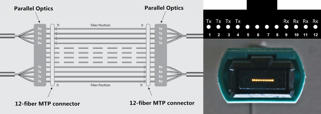
12-fiber-MTP-parallel-connection

Optical transceiver light source — Another complementary technology for parallel transmission is the light source of parallel optics—VCSELs (Vertical Cavity Surface Emission Lasers). Comparing with the edge-emitting semiconductor lasers in the traditional optics, VCSELs have better formed optical output which enables them to couple that energy into optical fibers more efficiently. In addition, VCSELs emit from the top surface, they may be tested while they are part of a large production batch (wafer), before they are cut into individual devices, which dramatically lowers the cost of the lasers. The following chart is about the comparison between VCSELs and edge-emitting semiconductor lasers. Cheaper to manufacture, easier to test, less electrical current required, supporting higher data rate, parallel optics using VCSELs could be a better choice to reach 40/100GbE transmission compared with traditional serial optics.

Parallel Optics for 40/100GbE Transmission

IEEE has already included physical layer specifications and management parameters for 40Gbps and 100Gbps operation over fiber optic cable. Two popular parallel optics solutions for 40Gbps and 100Gbps over multimode fibers are introduced here. For 40G, 40GBASE-SR4 transceiver is usually used, which requires a minimum of eight OM3/OM4 fibers for a transmit and receive link (4 fibers for Tx and 4 fibers for Rx). 100GBASE-SR4 transceiver (eg. QSFP-100G-SR4) is for 100Gbps transmission, which works through 4x25Gb/s 850nm VCSEL-based transmitter to achieve maximum link length of 100m on OM4 multimode fiber.

Conclusion

Parallel optical communication uses multiple paths to transmit a signal at a greater data rate than the individual electronics can support. Parallel transmission can either lower the cost of a given data rate (by using slower, less expensive optoelectronics) or enable data rates that are unattainable with traditional serial transmission. The capabilities and uses of parallel optics and MPO technology continue to evolve and take shape as higher-speed fiber optic transmission, including 40/100GbE. It is uncertain that parallel optical communication would be the trend in the future.


User's Guide To Third-Party Fiber Optic Transceivers Installation

2016-07-21 15:12:09 | Fiber Optic Transcei

Are you still hesitating to use third-party fiber optic transceivers? Maybe you haven’t noticed that the third-party ones are already predominant in the telecommunication market. Installing third-party fiber optic transceivers is relatively easy, providing you are using a transceiver that is MSA compliant and compatible with your brand of networking equipment. The following guide explains how to install third-party fiber optic transceivers:

1) Make sure you have the correct transceiver module for your device. Your device manual should contain a list of compatible transceiver models. The third-party transceiver module you purchase should also indicate which name brand manufacturer it is compatible with. For example, Fiberstore’s AFBR-79EEPZ QSFP+ transceiver is 100% compatible with Avago’s AFBR-79EEPZ. And their Cisco Linksys MGBT1 is 100% compatible with Cisco’s MGBT1.

2) Make sure you have the correct equipment and safety gear, such as a grounding device (e.g. ESD-preventative wrist strap), to prevent electrostatic discharge from damaging sensitive transceivers. If set down, fiber optic transceivers should be placed on a clean and static-free area, such as an antistatic mat.

3) Ensure that both the device’s transceiver ports and the transceiver’s plugs are clean and free of dust or oxidation. If the transceiver is new and won’t be used immediately, do not remove the dust plug. The dust plug at the end of a transceiver should only be removed at the time a fiber optic cable is inserted, and fiber optic cables should only be plugged into a transceiver after it is completely installed.

4) Properly orient the transceiver with the device slot. If your transceiver has a bail clasp (locking handle), pull it down until it clicks into a horizontal position. When installing a transceiver into a top slot, the bail clasp will typically be facing up when the transceiver is installed and locked into place. When installing transceivers into bottom slots, the bail clasp will typically be facing down when the transceiver is locked into place. Different devices can have different module socket configurations, so make sure you install the transceiver with the correct clasp-up or clasp-down orientation. For SFP and SFP+ transceivers, look for TX (transmit direction) and RX (receive direction) markings, or arrowheads, which will help you identify the proper orientation for the transceiver. Unnecessary removal and insertion should be avoided to prevent damaging both the transceiver and the device.

transceiver-graphic

5) When you slide the transceiver into the device slot there should be an audible click to indicate that the transceiver is in place. Press the transceiver firmly in using your thumb. To ensure the transceiver is secure, lightly tug on it and try removing the module without releasing the bail clasp.

transceiver-insert

6) If installing more than one transceiver, repeat steps 1-5 until all transceivers are installed. After all transceiver modules have been inserted, it’s time to remove the dust plugs on any cable-ready modules and begin connecting fiber optic cables. It is recommended that you remove the dust plug on the fiber optic cables first, and inspect and clean the end-faces of the connecting cables. Then remove the dust plug on the transceiver just before the cable is plugged in. This will keep the sensitive components inside your third-party fiber optic transceiver module protected as long as possible.

Learning how to install fiber optic transceivers is very helpful even though you are not a professional telecom engineer. As long as you follow the six steps outlined above, you should be able to install most form-factors of third-party transceiver modules without any hitches. For XENPAK compatible transceivers, you will need a flathead screwdriver to tighten the installation screws in the transceiver’s faceplate into the faceplate of the connecting device.


High-density Fiber Patch Panel Solutions in Data Centers

2016-07-19 15:41:38 | Fiber Patch P

Nowadays, space is often at a premium in data centers and SAN environments, making density more critical than ever. High-density fiber optic solutions offer the users performance and reliability. Using a comprehensive solution of high-density fiber enclosures or patch panels with either adapter panels or pre-terminated cassettes provides a complete fiber cross-connect patching solution for applications where maximum density is demanded.

Basis of High-density Fiber Patch Panels

The fiber patch panel, or fiber enclosure, is built and designed for efficient cable organization, management and protection within the racks. High-density fiber patch panel consists of a panel enclosure and modular HD cassettes, which can connect a 40G/100G fiber network feed (using MTP cable) and segment it into standard LC connections in order to interface with 10G devices. The cassettes are housed in a space-saving, rack-mountable, panel enclosure that can hold different amounts of cassettes, depending on the installation requirements.

fiber enclosure

What Can High-density Fiber Patch Panel Achieve?

The high-density patch panel can provide fast and easy deployment of high-density interconnects and cross-connect in data centers. The following are some advantages of using high-density fiber patch panels.

Simplify Cabling Deployment: With the fiber patch panel in place, there is no need to run long jumpers across the room, under the floor or in overhead conveyance. You only need to run a short fiber patch cable instead from your SAN or network switch up to the fiber patch panel/enclosure.

Space-saving: High-density fiber patch panel is one of the best space savers in the data center. It helps to increase port density by allowing you to fit more cables into a smaller space. Most importantly, it allows you to save space and stay organized.

Increase Port Density: Besides better space optimization, high-density patch panel can achieve double the port density in 1U of rack space. This allows for density increases and technology changes without a complete tear-out and replacement of existing infrastructure.

Ease of Installation: As described above, cassette is a part of the patch panel. When installing the cassette, no tools are required in the panel enclosure. And using push-pull tabs, connections can easily be locked or unlocked in the panel. Each cassette features factory terminated connectors that reduce the time and labor required of field connector terminations.

Flexibility and Adjustability: Fiber patch panels can connect different generations of equipment, such as 10G, 40G, 100G in a simple panel-cassette system. And network reconfigurations are highly adjustable due to the modular cassette system.

Cost-effective Solution for 40G/100G Network: Employing a high-density fiber patch panel is the most effective solution for overcoming cabling congestion associated with 40G/100G network connections as the modular plug-and-play cassettes can be changed when higher bandwidth becomes needed. It can manage, allocate and control the connections of network equipment of varying bandwidths. Cable management is simplified because the fiber patch panel can be changed or expanded by installing a new cassette instead of running new cables. By simply patching the 40G MTP cables at the back and the standard LC patch cable to devices in the front of the cassette, the IT staff don’t need to pull a new fan-out cable each time they need a new connection. Modular cassettes allow to expand whenever you need to accommodate the necessary bandwidth and connectors.

Modular cassettes

Summary

High-density fiber patch panel offers the highest level of scalability and highest density in the market. They enable a seamless distribution for bandwidth from 100G to 40G to 10G. FS.COM provides high-density fiber patch panels with various configurations. Any one of them would be an excellent option for your network. More details, visit www.fs.com or contact us over sales@fs.com for the detailed information.

Source: http://www.fiberopticshare.com/


Why Choose Fiber Optic Cables in AV Systems?

2016-07-18 12:24:06 | Fiber Optic Cable

As audio and video technologies continue to evolve, AV systems are continuously challenged with supporting high resolution video, audio, and control signals. The combination of light and glass presents some unique properties that give AV professionals powerful tools in common AV applications. A fiber optic cable can be used to send high resolution video, audio, and control signals on a single fiber over 30 km (18.75 miles), and avoids the risk of signal loss or degradation, ground loop hums, and electrical interference. Because transmission of content is inherently secure and immune to outside interference, fiber applications are favored in government, military, and medical environments. This article will mainly introduce four advantages of the installation of fiber optic cables in AV applications.

High Resolution Video, Audio, and Control Signals

Fiber optic cables are low-loss channels that enable transmission of high resolution video, audio, and control signals over long distance. Losses in fiber optic cables are 0.2 to 3.5 dB/km, compared to 60 dB/km for legacy RG6 coaxial cable at 100 MHz. The low-loss nature of single-mode fiber cables can enable transmission of WQXGA 2560x1600 video signals up to 30 km. Due to these advantages, fiber optic cables are widely used in campuses, sports stadiums and large office buildings, etc. Besides, installing fiber optic cables with extremely high bandwidth can ensure that future applications can be addressed with today’s fiber installations.

Easy to Install

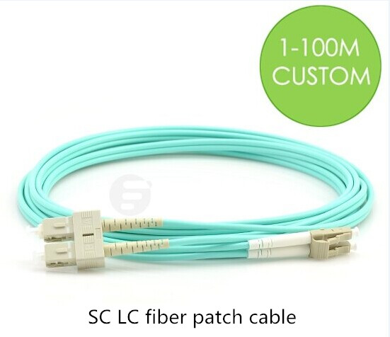
Fibers consume very little space in conduit and cable trays, and are easy to pull. For example, duplex fiber optic cable can transmit high resolution video signals but is only a fraction of the size of a coaxial cable. Because of fiber optic cables’ small size, the installation is much easier especially in medical applications where there is often insufficient space for thicker cables. Besides, today’s field termination kits make fiber easier to terminate than other types of cabling. Simply striping, cleaving, and inserting fibers into fiber optic connectors, you can get a high quality, reliable splice in minutes. And you can also choose pre-terminated fiber cables, such as LC patch cable or SC LC fiber patch cable (as shown below). The connectors you specify are pre-terminated for you, and the fiber cables you specify are cut to the proper length that you need. When the installation is over, you can just plug and play fiber optic system.

SC LC fiber patch cable

Safe for Sensitive and Hazardous Environments

Unlike copper cables, fiber optic cables are largely comprised of glass, which does not carry electrical current, radiate energy, or produce heat or sparks. So they can be safely installed in hazardous environments, such as oil refineries, mining operations, or chemical plants, without the danger of generating an electrical spark. Applications using sensitive electronics, such as medical environments, also benefit from the lack of electrical emissions with fiber optic systems. Fiber optic applications have helped the medical field advance tremendously over the past decade. They not only allow the physician to see inside specific areas of the body and perform surgery on hard-to-reach areas, but also provide a quicker and more accurate analysis of blood work.

Low Total Cost

Fiber optic systems may provide a lower total cost of ownership over the life of the system when compared to a coaxial or twisted pair solution. In copper systems, old cables need to be removed and new cables to be pulled for each system upgrade. While fiber optic cables with high bandwidth can be reused through multiple system upgrades. In addition, fiber optic cables typically consume less power and produce less heat than copper wires, thus reducing both electrical and cooling costs. Moreover, fiber optic systems can be monitored and serviced from the main equipment room without disrupting activities in work areas.

Conclusion

Fiber optic cables provide unique advantages in an AV system, particularly in secure and long distance applications. Choosing the proper cable depends upon the number of fibers required, installation location, topology, and the overall design of the system. Cable constructions are available for both indoor and outdoor applications to provide a solution for virtually any AV system.


Introduction to BiDi Optical Transceivers

2016-07-17 14:59:00 | Fiber Optical Transc

In the past few decades, a new class of pluggable optical transceivers have been developed that send and receive optical signals end-to-end over a single fiber strand. This reduces by half the amount of fiber required for that same total data transmission. This factor-of-two improvement can lead to substantial cost savings especially in campus environments with large numbers of connectivity endpoints.

Bi-Directional transceivers, called BiDi’s for short, use two different wavelengths to achieve transmission in both directions on just one fiber. The modules are deployed in pairs, one for the upstream (“U”) direction and another for the downstream (“D”). The standard defining these parts is the IEEE 802.3ah Gigabit Ethernet 1000BASE-BXnn (nn= transmission reach in kilometers) specification for point-to-point Ethernet in the First Mile (EFM) applications.

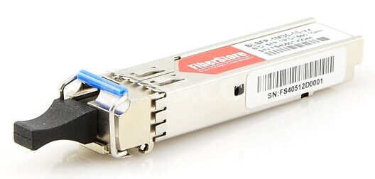
BiDi transceivers

The value of the BiDi solution derives from the reduction in the use of fibers by a factor of two. There are many situations in real-world networks where this reduction is extremely important if not absolutely required. As mentioned above, the IEEE802.3ah specification defining BiDi’s mentions point-to-point Ethernet in the First Mile (EFM) applications. In addition, BiDi transceivers can be of great use in any situation where only limited fibers or limited conduit space is available. Other common applications include: digital video and Closed Circuit TeleVision (CCTV) applications and high-density switch-to-switch port interconnection.

BiDi Technology…how they work…

As mentioned above BiDi transceivers are deployed in matched pairs, one for the upstream (“U”) direction and another for the downstream (“D”), each part transmitting at a different wavelength. The figure below depicts the details of such a matched set of BiDi transceivers. In this example, the two wavelengths utilized by the BiDi pair are 1310nm and 1490nm. Typically the “Upstream” or “U” transceiver transmits at the shorter of the two wavelengths and the “Downstream” or “D” module the longer wavelength.

The key additional technology present in BiDi’s that is not present in standard 2-fiber transceivers is the “Diplexer”. The Diplexer acts simultaneously couples the locally transmitted wavelength onto the single fiber while “splitting” off the received wavelength so it is directed at the receiver.

Economic Case for BiDi’s

The value of the BiDi solution derives from the reduction in the use of fibers by a factor of two. There are many situations in real-world networks where this reduction is extremely important if not absolutely required. As mentioned above, the IEEE802.3ah specification defining BiDi’s mentions point-to-point Ethernet in the First Mile (EFM) applications. In addition, BiDi transceivers can be of great use in any situation where only limited fibers or limited conduit space is available. Other common applications include: digital video and Closed Circuit TeleVision (CCTV) applications and high-density switch-to-switch port interconnection.

The simplest economic case for BiDi’s is probably a campus environment requiring fiber connectivity to a large number of endpoints. For example, most universities campuses are spread over a fairly wide area and required high-speed (read: fiber) connectivity between campus core resources (e.g., databases, computing resources, common internet access, etc.) and a large number of classrooms, dorm rooms, and faculty and administrative offices. The following is a simple economic model to demonstrate the savings possible in such an environment using BiDi versus standard 2-fiber transceivers.

So, for a campus environment where average link length is greater than 800 feet, the BiDi solution is the right decision. In an real world example, a large university campus lighting 400 GbE fiber links with an average length of 1600 feet used BiDi’s to save $32,000 versus using 2-fiber transceivers.

FS.COM BiDi Offering

FS.COM offers BiDi transceivers in the SFP form-factor supporting 1GbE for all major switch brands like Cisco, HP, Juniper, Extreme, Brocade, etc. We offer a 1Gbps SFP BiDi’s to cover a wide range of distances including: 10km, 20km, 40km, 80km and 120km, all of which are ROHS compliant. To aid in turn-up and maintenance of BiDi links, all FS.COM BiDi transceivers support Digital Diagnostics Monitoring (DDM as defined in standard SFF-8472) allowing real-time monitoring of parameters of the fiber SFP, such as optical output power, optical input power, temperature, laser bias current, and transceiver supply voltage.