Fiber Optic Tech

Sharing various fiber optic news, inforamtion, topics, etc.

24-fiber MPO/MTP Solution for 40/100G Migration

2016-03-22 17:36:22 | 日記

Since IEEE 802.3ba 40GBASE-SR4 and 100GBASE-SR10 were ratified in 2010, 24-fiber connectivity has been adopted as the ideal migration solution in the data center. Using 24-fiber cabling throughout an entire channel provides extra flexibility, as users can easily migrate from 10G to 40G or 100G by simply swapping out the connectivity at the end of the channel. Pre-terminated cabling using 24-fiber connectors provides double the density of 12-fiber cabling in the same footprint, reducing the cabling required, allowing for fewer cable pathways, and improving airflow in data centers. Next we will take a closer look at the advantages of 24-fiber MPO/MTP solution in 10G to 40/100G migration.

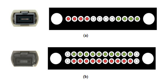
In choosing the migration path from 10G to 40/100 G, there are generally two options: the 12-fiber MPO/MTP solution or 24-fiber MPO/MTP solution. A 12-fiber MPO/MTP connector is used for 40 GbE (data rate up to 40Gbps, 4 x 10 Gbps). But among the 12 fibers, only 8 optical fibers are required—4 for Tx and 4 for Rx, and each channel has a transmission rate of 10 Gbps (usually use the 4 left and 4 right optical fibers, and the inner 4 optical fibers are left unused). And for 100 GbE (data rate up to 100 Gbps, 10 x 10 Gbps or 4 x 25 Gbps), there are two solutions. One is to use two 12-fiber MPO/MTP connectors, one transmitting 10 Gbps on 10 fibers and the other receiving 10 Gbps on 10 fibers. The other is to use a 24-fiber MPO/MTP connector. Among the 24 fibers, only 20 fibers in the middle of the connector are used to transmit and receive at 10 Gbps and the 2 top and bottom fibers on the left and right are unused. Why the 24-fiber is superior to 24-fiber? We’ll see the advantages from the following aspects.

12-fiber-vs-24-fiber MPO MTP

Maximum Fiber Utilization

Using 24-fiber trunk cables with 24-fiber MPO/MTP connectors on both ends to connect from the back of the switch panel to the equipment distribution area can maximum the fiber utilization. For 10G applications, each of the 24 fibers can be used to transmit 10 Gbps, for a total of 12 links. For 40G applications, which requires 8 fibers (4 Tx and 4 Rx), a 24-fiber trunk cable provides a total of three 40G links. For 100 GbE, which requires 20 fibers (10 Tx and 10 Rx), a 24-fiber trunk cable provides a single 100G link (24-fiber solution is the more recommended configuration to used for 100 GbE than 12-fiber solution). This recoups 33% of the fibers that would be lost with 12-fiber trunk cables, providing a much better return on investment.

Reduced Cable Congestion

24-fiber trunk cables provide more amount of fiber in less space. For instance, it takes three 12-fiber trunk cables to provide the same number of links as a single 24-fiber trunk cable—or about 1-1/2 times more pathway space for a 40G application.

Increase Fiber Density

Density in fiber switch panels is critical as today’s large core switches occupying upwards of 1/3 of an entire rack. 24-fiber MPO connectors offer a small footprint which can ultimately provide increased density in fiber panels at the switch location. In addition, with fanout technology, a 24-fiber MPO cable can be designed with a 24-fiber MPO on one end and 12 duplex LCs on the other end which is an ideal solution for high density 40/100 GbE migration.

Simple and Cost-effective

24-fiber MPO/MTP solution is a simple and cost effective migration path from 10G to 40/100G Ethernet. It effectively supports all three applications—10, 40 and 100 GbE. Data center managers can easily migrate to higher speeds, with less time and complexity, as 24-fiber solution offers guaranteed performance for 10, 40 and 100G applications, upgrading the cabling infrastructure is as simple as upgrading the fan-out cables or cassettes and fiber patch cords to the equipment.

24-fiber MPO/MTP solution provides an efficient way to migrate your network from 10 to 40 and 100 GbE. Choosing the right migration path not only helps you reach maximum benefit but also cut down the expenditures. Of course, choosing a good vendor is also a must. Fiberstore (FS.COM) may be your good choice. For more information, please contact us via sales@fs.com.


40 Gigabit Ethernet Cabling Solutions With MPO Technology

2016-03-18 17:21:53 | 日記

The increasing demands of bandwidth and high speed drive the emergence of 40 GbE. MPO technology with multifiber connectors offers ideal conditions for setting up high-performance data networks in data centers to achieve greater bandwidth and handle future requirements. This technology makes scaling and migration to network operation with 40/100 Gigabit Ethernet all the easier and more efficient. This article will introduce the practical application of MPO technology, which shows the solutions for 40 Gigabit Ethernet.

MPO Components

MPO connector (multi-fiber push-on and also as multi-path push-on) is a multi-fiber connector defined according to IEC 61754-7 and TIA/EIA 604-5. It is the main component in MPO technology that can accommodate up to 72 fibers in the tiniest of spaces, comparable to an RJ45 connector. MPO connectors are most commonly used for 12 or 24 fibers. In order to provide an introduction and basic information to the reader, this section begins with a presentation of the components needed for a parallel optical MPO connection. The MPO connectors can contact up to 72 fibers in a single connection. A connection must be stable and its ends correctly aligned, which is essential for achieving the required transmission parameters. A defective connection may even damage components and cause the link to fail altogether.

MPO connectors are available in a female version or a male version (with pins) as shown in the following picture. The pins ensure the exact alignment of the fronts of the connectors, and also they ensure the end faces of the fibers are not offset.

and precious-connector 

Noses and guide grooves on the top side are the two other clearly visible features, which ensures the adapter hold the connector with the correct ends aligned with each other. Based on the placement of the key, two types of MPO adapters are available. One is “key-up to key-down”. It means the key is up on one side and down on the other. The two connectors are connected turned 180° in relation to each other. The other one is “key-up to key-up”. It means both keys are up. The two connectors are connected while in the same position in relation to each other.

Connection Rule

Always use one male connector and one female connector plus one MPO adapter when creating a MPO connection (see the following picture).

and precious-connector-adapter

Never connect a female to a female or a male to a male. It should be connected with a male and a female as stated above. With a female-to-female connection, the fiber cores of the two connectors will not be at the exact same height because the guide pins are missing. That will lead to losses in performance. A male-to-male connection has even more disastrous results. There the guide pins hit against guide pins so no contact is established. This can also damage the connectors.

Never dismantle a MPO connector. The pins are difficult to detach from a MPO connector and the fibers might break in the process. In addition, the warranty becomes null and void if you open the connector housing.

MPO Cables

MPO cable has the advantages of shorter installation times, tested and guaranteed quality and greater reliability. It has several different kinds of types.

MPO trunk cable with two MPO connectors (male/female) on both end of the cable serves as a permanent link connecting the MPO modules to each other, which is available with 12, 24, 48, 72 fibers. MPO trunk cable requires greater care in planning but has a number of advantages, such as higher quality, minimal skew, shorter installation time, better protection, smaller volume of cable and lower total costs.

MPO harness cable is terminated with a male/female connector on the MPO side and several duplex LC/SC connectors on the other side. MPO harness cable provides a transition from multi-fiber cables to individual fibers or duplex connectors. For example, 8 fibers 12 strands MPO harness cable has eight LC high fiber density connectors and a MPO connector, which is convenient for wiring and management system in 40G network with stable performance.

MPO Solutions for 40 Gigabit Ethernet Cabling

OM3 and OM4 fiber optic cables put in a parallel optical connection, terminated with MPO/MTP connectors. These are the ingredients for 40 GbE technology in a structured cabling environment. Parallel optical channels with multifiber multimode optical fibers of the categories OM3 and OM4 are used for implementing 40 GbE. The small diameter of the optical fibers poses no problems in laying the lines, but the ports suddenly have to accommodate four or even ten times the number of connectors. This large number of connectors can no longer be covered with conventional individual connectors. So the 802.3ba standard incorporated the MPO connector for 40GBASE-SR4.

Conclusion

MPO connectors and cables are the core components of a 40G parallel optical link. The connecting link determines whether the insertion loss exceeds the attenuation budget and whether the return loss is high enough. In the end, the desired bandwidth can only be reached if all components in a parallel optical link satisfy the highest requirements.


Fiber Ribbon Solution for the 10G to 40/100G Migration

2016-03-15 14:57:50 | 日記

With end-user connectivity now possible through various user devices, fiber optic cables have become the ubiquitous transport medium in the data center network. A well designed cable, namely the ribbon fiber cable which can improve the operation of the electronics potentially, as well as minimize the amount of power required for air conditioning is favored by many users. It is important to examine and consider both how and why an optical fiber ribbon cabling solution should be deployed for new 40Gbs /100Gbs installations. This article will explain the reasons from the follow three aspects.

Fiber Requirements

For every optical network, standards for fiber performance must be followed to ensure proper operation under planned conditions of the network. Typically, this means that both distance and link loss budgets must be established for the data center infrastructure. Two standards define the fiber performance that must be adhered to in the data center. They are the IEEE802.3ba standard for 40/100Gbs Ethernet and the TIA-942 Telecommunications Infrastructure Standard for Data Centers. Currently, both 1 and 10Gbs systems use a single fiber to transmit data at the requisite speed. This means one fiber and one connection each per transmit and receive signal channel. The process is accomplished using LC duplex connectors on fiber jumpers for one channel connection that can be applied to 1 and 10Gbs systems.

Form Factors

The transceiver form factor differs as speeds increase. In the following chart, we see that different data transmission schemes in the leftmost column are supported by various form factors. Since both 40G and 100G solutions can be installed using “4 by” parallel optics (i.e. four separate channels transmitting and receiving) it may be prudent for the data center manager to select a form factor for “future proofing” that uses this protocol, so that little or no changes are needed. The green box in the chart contains the “standard” transceiver in use today for 40Gbs. For instance, Finisar FTL4C1QE1C compatible 40GBASE-LR4 QSFP+ transceiver uses 4 parallel fibers for transmission and 4 lanes to achieve 10km over single-mode fiber with duplex LC connectors. The red box outlines a four lane solution for 100Gbs systems.

data transmission

Connectivity and Cable Design

Today, MTP connector is the most prevalent connector type in 40G system and can easily terminate the fiber ribbon cable. It is commonly available in preterminated form—as a pigtail to be spliced onto a 12-fiber ribbon, or as a MTP patch cord which is terminated on each end. Many end-users are now using preterminated cables where the cable is factory terminated with MTP connectors and/or simplex or duplex connectors to ensure the highest quality connector insertion loss and return loss performance and to expedite the cable installation.

Push-Pull MPO patch cable

Fiber ribbon cables were initially built according to outside plant fiber cable standards. The designs later migrated to armored versions, dry outside plant cables, and riser and plenum rated indoor cables. The fiber density, particularly as fiber counts increase in the data center, is a very attractive feature of these types of cables. In addition, ribbon cable can be considered as an excellent choice in the data center environment because of the good crush resistance design.

Conclusion

With so many advantages, ribbon fiber cables have been widely deployed in data center communications. The ribbon fiber cable promotes a seamless migration from 10G to 40/100G. The ribbons in fiber optic cables are best suited for future expansion, since the transmission protocols progress to higher and higher data rates. It can save much time and money when upgrades are performed on existing data center end equipment while ensuring optimum data center installation speed, performance, connectivity, and cost efficiency.


Cabling and Transceiver Options for 40 Gigabit Ethernet

2016-03-14 10:53:15 | 日記

40 Gigabit Ethernet era is already upon us and makes a contribution to satisfying the increasing demands of higher throughputs and bandwidth. The 40-Gbps Ethernet transfers data at a rate of 40 gigabits per second over Ethernet. The biggest market for 40G Ethernet (40GbE) is in data center for interconnection links with servers and storage area networks. How to deploy 40G Ethernet? This article will introduce some information related to 40G cabling and transceivers options.

Cables for 40 Gigabit Ethernet

40G cables can provide inexpensive and reliable 40G speed connections using either copper cables with distances reaching up to 30ft (~10 meters length) or active optical cables reaching even 300ft(100 meters). Cables can be divided into different types according to different criteria. There are generally two types: fiber and copper cables.

  • Fiber Cables: active optical cable (AOC) assemblies were invented to replace copper technology in data centers and high performance computing (HPC) applications. The 40G QSFP+ AOC is a parallel 40Gbps quad small form factor pluggable (QSFP+) active optical cable, which supplies higher port density and total system cost. The QSFP+ optical modules provide four full-duplex independent transmit and receive channels, each are able of 10Gbps operation 40Gbps aggregate bandwidth of at least 100m multimode fiber.
  • Copper Cables: QSFP+ to QSFP+ copper cable and QSFP+ to 4SFP+ breakout copper cable are the two common types of QSFP+ cables. QSFP+ to QSFP+ copper cables are hot-removable and hot-insertable. A cable consists of a cable assembly that connects directly into two QSFP+ modules, one at each end of the cable. QSFP+ to 4 SFP+ breakout copper cable is with one QSFP+ on one end and four SFP+ on the other end. It allows a 40G Ethernet port to be used as four independent 10G ports thus providing increased density while permitting backward compatibility and a phased upgrade of equipment. QFX-QSFP-DAC-1M
40G Optical Transceivers Types

40G optical transceivers, compliant to the IEEE standards mainly include CFP and QSFP (Quad Small Form-factor Pluggable). CFP stands for C form-factor pluggable and it is a multi-source agreement to produce a common form-factor for the transmission high-speed digital signals. Nowadays, QSFP is more favored than CFP, and it mainly has the following three types:

  • 40GBASE-SR4 It reaches 40-Gbps Ethernet over four short-range multimode fiber optic cables and supports link lengths of 100m and 150m respectively on laser-optimized OM3 and OM4 multimode fiber cables. In this process, the multimode fiber uses parallel-optics transmission instead of serial transmission due to the 850nm vertical-cavity surface-emitting laser (VCSEL) modulation limits. Parallel-optics transmission uses a parallel optical interface where data is simultaneously transmitted and received over multiple fibers and the interfaces are 4x10G channels on four fibers per direction.
  • 40GBASE-LR4 It reaches 40-Gbps Ethernet over four wavelengths carried by a single long-distance singlemode fiber optic cable and supports link lengths of up to 10 km over single-mode fiber with duplex LC connectors. It operates at a wavelength of 1310 nm. The 40 Gigabit Ethernet signal is carried over four wavelengths with 10G on each wave. It is designed to use in switches, routers and data center equipment where it provides higher density and lower cost when compared with standard SFP+ modules.
  • 40GBASE-CR4 It is a direct attach cable segment with the QSFP+ modules attached to each end of the cable. It reaches 40-Gbps Ethernet over four short-range twinaxial copper cables bundled as a single cable and supports link lengths of up to 10 km over a standard pair of G.652 single-mode fiber with duplex LC connectors. The QSFP+ modules are plugged into the QSFP+ ports on the switch or computer interface. Before you choose to use the 40GBASE-CR4 , please make sure the QSFP+ modules on the cable support the QSFP+ port on your switch or computer interface.
Conclusion

As the main fiber optical manufacturer in China, Fiberstore provides a wide range of 40G cables and optical transceivers, such as Cisco QSFP-H40G-CU5M copper cable, Juniper JNP-QSFP-40G-LR4 QSFP+ transceivers, etc. All our cables can meet the ever increasing need to cost-effectively deliver more bandwidth, and can be customized to meet different requirements.


Connectivity Options for 10 Gigabit Ethernet

2016-03-10 10:19:05 | 日記

Since March 1999, the Ethernet industry has been working on providing solutions to increase the speed of Ethernet from 1 to 10 gigabits per second. For enterprise LAN applications, 10 Gigabit Ethernet enables network managers to scale their Ethernet networks from 10 Mbps to 10,000 Mbps, while leveraging their investments in Ethernet as they increase their network performance. There are various types of cables and transceivers available for making Ethernet connections at speeds of 10 Gigabit per second. This article will illustrate both the copper and fiber connectivity options for 10 Gigabit Ethernet.

Transceivers

Standards bodies initially offered several options for the 10-Gigabit transceiver. The one that ultimately evolved as most popular in commercial data center usage was the XFP transceiver. In recent years an extension of the SFP transceiver was standardized for use with 10 Gigabit Ethernet and named SFP+. SFP+ has three outstanding advantages. First of all, it was smaller than the XFP form factor allowing for much more dense packaging of ports on (primarily) switches. Secondly, a new type of very short distance copper cable was developed which uses the same mechanical form factor as the optical transceiver and is capable of carrying 10Gbps Ethernet data. This cable type is called direct attach copper cable which will be introduced later. SFP+ has now become the predominant 10G Ethernet connector type.

455883-B21

Fiber Cables

Fiber cables consist of the cable itself and the connectors on the ends. There are multiple choices for cable type and for connector type. The difference in cable choices come from the distance limitations encountered with the various types of optical transmission. The commonly available types of fiber cables include: SR for connections of up to 300 m in length, LR for connections of up to 2 km in length and ER for connections of up to 10 km in length.

Copper Cables
  • 10GBASE-T For 10-Gigabit Ethernet cabling, the standards body determined that even enhanced Cat5e UTP traditional Ethernet cable would not be able to carry the signal reliably for any significant distance. So a new specification which still uses RJ45 connectors was introduced and is commonly referred to by its standards name 10GBASE-T. It calls for a 4-wire twisted pair cable with even more strinent limitations on cross-talk.
  • CX4 CX4 is a cable type generally associated with an alternative networking technology called InfiniBand. CX4 cable can also be used in 10Gigabit Ethernet connections. It uses a coaxial copper cable and can support cable lengths of up to 15m.
  • SFP+ As discussed above, one of the advantages of the SFP+ connector type was that a new type of very-short-distance copper cable was developed which uses the same mechanical form factor as the optical transceiver and is capable of carrying 10Gbps Ethernet data. This cable type namely SFP+ direct attach copper cable is a fixed assembly that is purchased at a given length, with the SFP+ connector modules permanently attached to each end of the cable. It provides high performance in 10 Gigabit Ethernet network applications, using an enhanced SFP+ connector to send 10 Gbps data through one paired transmitters and receivers over a thin twinax cable.

To conclude, 10 Gigabit Ethernet has become the technology of choice for enterprise, metropolitan, and wide area networks. Choosing the right kind of connectivity options helps you ensure the proper and efficient performance of your networks. Fiberstore offers various kinds of fiber optical transceivers for 10 Gigabit Ethernet, such as the HP J9151A, NETGEAR AXM761 SFP+ transceiver and so on. Besides, cables for 10 Gigabit Ethernet can be customized according to your special requirements.