goo blog サービス終了のお知らせ 

Fiber Optic Tech

Sharing various fiber optic news, inforamtion, topics, etc.

Passive DWDM vs. Active DWDM

2017-03-01 10:08:34 | WDM

To keep pace with the rapidly growing volumes of data-network traffic driven by the growth of the Internet, service providers are always looking to increase the fiber capacity and wavelength spectral efficiency in their networks. DWDW (dense wavelength division multiplexing) is an optical multiplexing technology used to increase bandwidth over existing fiber networks. DWDM works by combining and transmitting multiple signals simultaneously at different wavelengths on the same fiber. It has revolutionized the transmission of information over long distances. DWDM can be divided into passive DWDM and active DWDM which will be illustrated in this article.

Passive DWDM

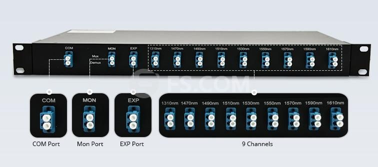
“Passive” refers to the passive DWDM MUX DEMUX element which is an unpowered, pure optical equipment. Passive DWDM systems have no active components, which means that no optical signal amplifiers and dispersion compensation modules (DCM) are used. The DWDM passive link is only determined by the optical budget of transceivers used. Passive DWDM system has a high channel capacity and potential for expansion, but the transmission distance is limited to the optical transceivers used. The main application of passive DWDM system is metro networks and high speed communication lines with a high channel capacity.

Active DWDM

Active DWDM system is built from transponders, providing full optical demarcation point agnostic to the routers, switches and ADMs within the network. Active DWDM offers a way to transport large amounts of data between sites in a data center interconnect setting. The transponder takes the outputs of the SAN or IP switch format, usually in a short wave 850nm or long wave 1310nm format, and converts them through an optical-electrical-optical (OEO) DWDM conversion. In long-haul DWDM networks, several EDFAs are installed sequentially in the line. The number of amplifiers in one section is determined by the fiber cable type, channel count, data transmission rate of each channel, and permissible OSNR value.

active DWDM

Besides, the maximum transmission distance of the active DWDM system also depends on the influence of chromatic dispersion—the distortion of transmitted signal impulses. When designing a DWDM network project, permissible values of chromatic dispersion for the transceivers should be considered, and, if necessary, chromatic dispersion compensation modules are included in the line. DCM fixes the form of optical signals that are deformed by chromatic dispersion and compensates for chromatic dispersion in fibers.

Passive DWDM vs. Active DWDM

Choosing passive or active DWDM system depends on your requirements and current setup. Because both of them have pros and cons.

Passive DWDM Pros: 1. Inexpensive - As mentioned above, less components are required, and less engineering time is required.

2. INITIAL Setup - Because of the colored optics there isn't a need to tune wavelengths for all of your connections. It's a matter of matching your colored optics and plugging it.

Cons: 1. Scalability - you are limited to colored optics, and less wavelengths on the transport fiber. As you grow, you would be required to have more passive devices. Furthermore, with the more passive devices, you have more difficulty to manage. And you will have to start managing the same wavelength on multiple passive devices and they could be serving different purposes on each depending on your setup.

2. Control - If you need to change a wavelength or connection for whatever reason, your option is limited to taking it out of service and disconnecting the physical cabling as the wavelength is tied to the optic.

Active DWDMPros:

1. Active can fit a lot more wavelengths (colors) onto a single fiber pair. The composite signal that is sent over a single fiber pair can carry more bandwidth than a passive of the same size, in turn you don't need as much physical fiber between your two sites (this really only applies if you require that much bandwidth). This is advantageous when distance is a problem because it allows you to get more out of a single leased fiber pair as opposed to passive.

2. Active setups grant you more control over your optical network, you can dynamically re-tune wavelengths without dropping connections (it's transparent to whatever is riding on that wavelength).

3. Scalability - Active can be easier to scale as your network grows (you can fit more wavelengths on the fiber, see above), but again - we're talking seriously big iron. I'll dig into it a bit more below.

Cons: 1. EXPENSIVE - Active DWDM setups are much more expensive compared to passive DWDM. If you don’t have long-distance requirements, don’t choose active DWDM.

2. Configuration - Depending on your vendor, configuration can be a serious undertaking, and require a solid understanding of optical networks. There are many more components in active builds.

Conclusion

Most of the time, DWDM operates with powered component like transponders. Further, after multiplexing the signals, they typically need active amplification to have any preferred reach. Without this, you're only going with a relatively short distance, which is not a good value for the expense of DWDM.


Evolution of Optical Wavelength Bands

2017-02-27 11:08:27 | WDM

As fiber optic networks have developed for higher speeds, longer distances, and wavelength-division multiplexing (WDM), fibers have been used in new wavelength ranges, namely "bands". Fiber transmission bands have been defined and standardized, from the original O-band to the U/XL-bands. This article will mainly illustrate the evolution of the typical fiber transmission bands used for different optical telecom systems.

Among these bands, the O-band, also called the Original-band, was the first band used in optical telecommunication because of the small pulse broadening (small dispersion); Single-mode fiber transmission began in the "O-band" just above the cutoff wavelength of the SM fiber developed to take advantage of the lower loss of the glass fiber at longer wavelengths and availability of 1310nm diode lasers.

DWDM

The E-band represents the water peak region while the U/XL-band resides at the very end of the transmission window for silica glass. The E-band (water-peak band) has not yet proven useful except for CWDM. It is probably mostly used as an extension of the O-band but few applications have been proposed and it is very energy-intensive for manufacture. The E-band and U/XL-bands usually are avoided because they correspond to high transmission loss regions.

To take advantage of the lower loss at wavelength of 1550nm, fiber was then developed for the C-band. The C-band is commonly used along with the development of ultra-long distance transmission with EDFA and WDM technologies. As transmission distances became longer and fiber amplifiers began being used instead of optical-to-electronic-to-optical repeaters, the C-band became more important. With the advent of DWDM (dense wavelength-division multiplexing) which enables multiple signals to share a single fiber, the use of C-band was expanded.

With the development of fiber amplifiers (Raman and thullium-doped), DWDM system was expanded upward to the L-band, leveraging the wavelengths with the lowest attenuation rates in glass fiber as well as the possibility of optical amplification. Erbium-doped fiber amplifiers (EDFAs, which work at these wavelengths) are a key enabling technology for these systems. Because WDM systems use multiple wavelengths simultaneously, which may lead to much attenuation. Therefore optical amplification technology is introduced.

Despite great expectations, the number of installed systems using all-Raman solutions worldwide can be counted on one hand. In the future, however, the L-band will also prove to be useful. Because EDFAs are less efficient in the L-band, the use of Raman amplification technology will be re-addressed, with related pumping wavelengths close to 1485nm.

Although CWDM is now considered as a low-cost version of WDM that has been in use, most do not work over long distances. The most popular is FTTH PON system, sending signals downstream to users at 1490nm (in S-band) and using low cost 1310nm transmission upstream. Early PON systems also use 1550 downstream for TV, but that is being replaced by IPTV on the downstream digital signal at 1490nm. Other systems use a combination of S, C and L bands to carry signals because of the lower attenuation of fibers. Some systems even use lasers at 20nm spacing over the complete range of 1260nm to 1660nm but only with low water peak fibers.

Although various wavelength bands of the O-, S-, C- and L- bands have come into use with the explosive expansion of the traffic in recent years, the optical fiber amplifiers for the O- and S-band wavelengths were not realized for many years because of many technical hurdles. C- and L-band most commonly used in fiber optic networks will play more and more important roles in optical transmission system with the growth of FTTH applications.

Originally published at http://www.china-cable-suppliers.com


Identify Various Ports on WDM Mux/Demux

2017-02-21 17:46:19 | WDM

In today’s world of intensive communication needs and requirements, fiber optic cabling has become increasingly popular. But considering the physical fiber optic cabling is expensive to implement for each individual service, using a Wavelength Division Multiplexing (WDM) for expanding the capacity of the fiber to carry multiple client interfaces is highly advisable. WDM MUX/DEMUX (Multiplexer/De-Multiplexer) is one of the most important components in WDM systems. But there are so many types of ports which are not so easy to identify. This article will illustrate various ports with different functions on WDM Mux/Demux.

Common Ports on WDM Mux/Demux

For WDM Mux/Demux, channel port and line port are the most common and necessary ports for normal operation of the WDM Mux/Demux.

Channel Port

CWDM uses 18 wavelengths ranging from 1270nm to 1610nm with channel intervals of 20nm. Channel ports on CWDM MUX/DEMUX is usually ranging from 2 to 18. DWDM uses the wavelength ranging from 1470nm to 1625nm usually with the channel port ranging from 4 to 96. Since DWDM Mux/Demux has a more dense channel spacing of 0.8 nm (100 GHz) or 0.4 nm (50 GHz), it is more suitable for high-density networks.

CWDM Channels

Line Port

There are two types of line port available for CWDM and DWDM MUX/DEMUX. One is dual fiber line port, and the other is single fiber line port. The wavelengths order and the applications of them are totally different. Dual-fiber line port is used for bidirectional transmission, which means the TX port and RX port of every duplex channel port supporting the same wavelength. The WDM MUX/DEMUXs with dual fiber line ports installed on the two ends of the network could be the same. Single-fiber line port only support one direction data flow. If you choose a single-fiber WDM MUX/DEMUX on one side of the network, there should be a single-fiber WDM MUX/DEMUX which supports the same wavelengths but has the reverse order on the TX port and RX port of every duplex channel port.

Special Ports on WDM Mux/Demux

1310nm Port and 1550nm Port

1310nm and 1550nm ports are wavelength ports of WDM MUX/DEMUX. Since a lot of optical transceivers use these two wavelengths for long-haul network, adding these two ports when the device does not include these wavelengths is very important. CWDM Mux/Demux can add either type of wavelength ports, but the wavelengths which are 0 to 40 nm higher or lower than 1310 nm or 1550 nm cannot be added to the device. However, DWDM Mux/Demux can only add 1310nm port.

Expansion Port

Expansion port which can be added on both CWDM and DWDM Mux/Demux is a special port to increase the number of available channels carried in the network. It means that when a WDM Mux/Demux can not meet all the wavelength needs, it is necessary to use the expansion port to add different wavelengths by connecting to another WDM Mux/Demux’s line port.

Monitor Port

This port is used to monitor or test the power signal coming out of a Muxed CWDM or before it gets demuxed from the signal coming through the fiber network usually at a 5% or less power level. Generally, it can be connected with measurement or monitoring equipment, such as power meters or network analyzers.

No matter the common ports or the special ports on WDM Mux/Demux have their own features and application. FS.COM WDM products designed for easy and fast implementation take up minimal space and use least power, thus providing the highest integration level of CWDM and DWDM networks. They can also provide complete solutions for CWDM and DWDM. Kindly contact sales@fs.com for more details if you are interested.


Understanding DWDM in Optical Communication

2016-12-13 11:49:12 | WDM

Without optical communication we might be still sending mail, going to the newsstand to buy a newspaper, sending mail and postcards and renting movies, no internet would have been possible, no digital communications as we know it.

Among the many unsung technologies that make all this possible, Dense Wavelength Division Multiplexing (DWDM) is without any doubt one of the most important. As a kind of WDM technology, DWDM has the capability to send multiple signals on the same fiber, using different wavelengths. DWDM devices combine the output from several optical transmitters for transmission across a single optical fiber. At the receiving end, another DWDM device separates the combined optical signals and passes each channel to an optical receive. One of the nice characteristics of the optical fiber is that different channel can travel one close to the other with very little, almost negligible in most cases, crosstalk. Thanks to DWDM, we’re now able to pack 10 TBits/s of traffic per single fiber and send it more than 1000Km.

DWDM started as high end transport technology, but made its way to regional and metropolitan network and finally into transceivers. Several generation of DWDM transceivers have already been released (XENPAK, X2, XFP, SFP, SFP+), providing networking equipment not only with the capability to transport a huge amount of data with a single fiber, simplifying cabling and reducing cost, but also reducing the number of equipment needed. Before, if an operator wanted to connect 2 switches located some tens of kilometers apart, it needed non-coloured optics on the switch, connected with the same kind of optics on the transport system transponder shelf, this last piece of equipment did the conversion from non-DWDM wavelengths to DWDM wavelengths before they were optically multiplexed and transported over the DWDM link, the opposite process at receiving site. With DWDM transceivers directly on the switch, they can be connected directly to the optical multiplexing gear. It is evident that this solution has numerous advantages.

DWDM

If it is clear that DWDM optics come with great advantages, but the device is more complex and more optical variables comes into play. With uncoloured optics everything is pretty simple , they come with a “distance” tag attached (10km, 40km, 300m), power budget is pretty much the only parameter that the end user should care about. With DWDM there is no specific target distance power levels are of course still important, but other parameter, such as OSNR (optical signal to noise ratio) and CD (chromatic dispersion) come into play, in fact, often specifications are given in the form of a combination of the three mentioned parameters.

An optical signal travelling on a fiber experiences an attenuation of about 0.2dB/Km, so if you want to transmit it for long distances it needs to be amplified along the way and probably more than once. Erbium doped fiber amplifiers (EDFAs) do exactly this, but, at every amplifying stage, noise is added to the signal. The longer you want to go, the more amplifiers you need, the noisier the signal at the end of the line. Below a certain OSNR, which depends on the device to device, becomes impossible to detect the signal with an acceptable bit error rate.

DWDM is ready made for long-distance telecommunications operators that use either point-to-point or ring topologies. It provides ultimate scalability and reach for fiber networks. Without the capacity and reach of DWDM systems, most cloud-computing solutions today would not be feasible. Establishing transport connections as short as tens of kilometers to enabling nationwide and transoceanic transport networks, DWDM is the workhorse of all the bit-pipes keeping the data highway alive and expanding.


How Much Do You Know About OADM

2016-11-23 16:38:09 | WDM

The OADM, short for optical add drop multiplexer, is one of the key components for dense wavelength division multiplexing (DWDM) and ultra wide wavelength division multiplexing (UW-WDM) optical networks. OADM technology is used to cost effectively access part of the bandwidth in the optical domain being passed through the in-line amplifiers with minimum amount of electronics.

An OADM can be considered as a specific type of optical cross-connect, widely used in wavelength division multiplexing (WDM) systems for multiplexing and routing fiber optic signals. They selectively add and drop individual or sets of wavelength channels from a dense wavelength division multiplexing (DWDM) multi-channel stream. OADMs are used to cost effectively access part of the bandwidth in the optical domain being passed through the in-line amplifiers with the minimum amount of electronics.

OADMs have passive and active modes depending on the wavelength. In passive OADM, the add and drop wavelengths are fixed beforehand while in dynamic mode, OADM can be set to any wavelength after installation. Passive OADM uses WDM filter, fiber gratings, and planar waveguides in networks with WDM systems. Dynamic OADM can select any wavelength by provisioning on demand without changing its physical configuration. It is also less expensive and more flexible than passive OADM. Dynamic OADM is separated into two generations.

A typical OADM consists of three stages: an optical demultiplexer, an optical multiplexer, and between them a method of reconfiguring the paths between the optical demultiplexer, the optical multiplexer and a set of ports for adding and dropping signals. The MUX multiplexes the wavelength channels that are to continue on from DEMUX ports with those from the add ports, onto a single output fiber, while the DEMUX separates wavelengths in an input fiber onto ports. The reconfiguration can be achieved by a fiber patch panel or by optical switches which direct the wavelengths to the MUX or to drop ports. All the light paths that directly pass an OADM are termed cut-through lightpaths, while those that are added or dropped at the OADM node are termed added/dropped lightpaths.

OADM works as follows: the WDM signals from line containing N wavelength channels enter the OADM "Main Input" side, depending on your business needs, from N wavelength channel, selectively from the road-side (Drop) required by the output wavelength channel, accordingly from the road-end (Add) enter the desired wavelength channel. Regardless of other local wavelength channel directly through the OADM, and routing wavelength channels multiplexed together, from the output terminals of the circuit of OADM (Main Output) output. The following picture shows the basic operation of an OADM.

basic-operation-of-oadm

Physically, there are several ways to realize an OADM. There are a variety of demultiplexer and multiplexer technologies including thin film filters, fiber Bragg gratings with optical circulators, free space grating devices and integrated planar arrayed waveguide gratings. The switching or reconfiguration functions range from the manual fiber patch panel to a variety of switching technologies including microelectromechanical systems (MEMS), liquid crystal and thermo-optic switches in planar waveguide circuits.

CWDM and DWDM OADM provide data access for intermediate network devices along a shared optical media network path. Regardless of the network topology, OADM access points allow design flexibility to communicate to locations along the fiber path. CWDM OADM provides the ability to add or drop a single wavelength or multi-wavelengths from a fully multiplexed optical signal. This permits intermediate locations between remote sites to access the common, point-to-point fiber message linking them. Wavelengths not dropped, pass-through the OADM and keep on in the direction of the remote site. Additional selected wavelengths can be added or dropped by successive OADMS as needed.

FS.COM provides a wide selection of specialized OADMs for WDM system. Custom WDM solutions are also available for applications beyond the current product designs including mixed combinations of CWDM and DWDM.