Fiber Optic Tech

Sharing various fiber optic news, inforamtion, topics, etc.

Three Ways Fiber Optic Transceivers Promote Data Center

2016-04-06 17:07:31 | Fiber Optical Transc

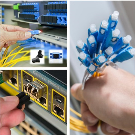
Data center has now become one of the most critical and dynamic operations in any business. With all the data processing and transmission, it is only critical that every design aspect and component of your data center is properly optimized, including its fiber optic transceiver technology. The transceiver and other optical components need to meet varied bandwidth requirement for storage, switch, and server applications. Now let’s see how the optical transceivers will promote data centers in the future.
Fiber-Optic-Transceivers

Small Package Makes Sense

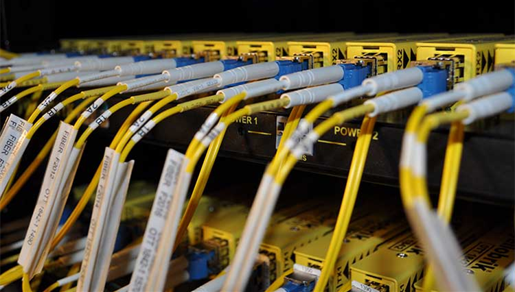
Optical transceivers are becoming smaller, but more powerful, which makes them an important piece in server technology. In fact, even though a transceiver is physically small, it can handle a network expansion or an entire install. This shrinking of transceivers allows for the improvement of servers. This reduces the overall footprint of servers and networks, which makes data centers smaller and streamlined. Optical transceivers also require lower power consumption, which means you get lower costs both in terms of design and electricity expenses.

Transceivers Promote High Speed Data Transfer

A growing number of enterprises are transiting to private and hybrid clouds, which drives the bandwidth and connectivity requirements. As high-speed data carrier, transceivers facilitate high speed data transfers. Enterprises that want to achieve faster transmission have to choose transceivers with high quality. There are many types of transceivers available in the market, such as SFP, SFP+, XFP, QSFP, etc. Each type of transceiver is designed to support different data rate. Capable of transmitting data at 10Gbit/s, 40Gbit/s, 100Gbit/s or even 120 Gbit/s, transceivers can realize the high-speed data transfer, ensuring bandwidth upgrades in enterprise data centers. Taking 10GBASE SFP+ modules for example, these hot-pluggable transceivers (eg. HP 455883-B21) deployed for 10 Gigabit Ethernet (GbE) applications, though designed physically small, support maximum data rate of 10.3125Gbps.

Data Center Makes up Big Transceiver Market

Optical components are always being improved, which can only mean good things for data center managers. According to recent numbers, 2016 and beyond will be huge for the data center market and optical components as more companies require efficiency in their networks. Data centers make up 65% of the overall 10G/40G/100G optical transceiver market. Shipment of 10G transceivers continue to grow, but still has plenty of space to develop, especially as industry experts expect the optical transceiver market is expected to reach $2.1 billion by 2019.

40G and 100G Transceivers Pave the Way

Consumers and technology experts can expect optical transceivers to improve as data centers grow and the cloud industry expands. Manufacturers have introduced transceivers that can transmit data at 40Gbps and 100Gbps, while some startups are investing millions in developing technology that can achieve higher speeds. These and other improvements can only mean good things for businesses and consumers.

It’s necessary to mention that there are more than three ways that transceivers promote data centers. Transceivers, a key component designed relative to the promotion of big data in data centers, are instrumental in managing big data. As a professional transceiver supplier, FS.COM provides a wide variety of fiber optic transceivers supporting different data rates, like SFP+ (eg. SFP-10G-LR), XFP (eg. XFP10GLR-192SR-L), QSFP (eg. QSFP-40G-CSR4). If you have any requirements, please contact us via sales@fs.com.


Fiber Optic Dust Caps in Your Fiber Systems

2016-04-05 17:42:27 | Fiber Optic Tools

What is the main purpose of fiber optic connector dust caps? To protect the connector end-face from dust? Not absolutely! Actually, a dust cap might also introduce dust and other contaminants to the polished end-face of a fiber optic connector in some cases. Then why use those fiber optic dust caps and what should be noticed when using them? This article will give you the answer.

Why Use Fiber Optic Dust Caps?

Dust is everywhere. Smaller dust particles that have a diameter of 1um or less can remain suspended in air for a very long time. Dust can easily find its way into a dust cap, and stow away until it has the opportunity to jump aboard your fiber optic connector end-face. Dust caps do a great job in protecting fiber optic connector end-faces from contact with objects that can scratch, chip, crack or otherwise physically damage the polished core of the fiber. Dust caps also provide ferrule protection and are ideal for protecting connectors from physical damage while in storage or in transit. If you accidentally drop a connector that's wearing a dust cap, chances are it will survive the fall. It is advisable to install dust caps on any fiber optic connector that is not actively in use.

Dust caps can be purchased alone, and some fiber optic connectors come with protective caps already installed. Typically, the cap is a sleeve or boot that is closed at one end and which fits tightly over the ferrule of the fiber optic connector.

Common Types of Fiber Optic Dust Caps

As mentioned above, almost all ports in fiber systems need dust caps to protect from damage or external contaminates when they are unused. Fiber optic adapters, connectors and fiber transceivers are the most commonly used optics in fiber system that need dust caps. These types of fiber optic dust caps are respectively called adapter dust caps, connector dust caps and transceiver dust caps.

  • Adapter Dust Caps – Used for protecting fiber adapters and couplers.
  • Transceiver Dust Caps – Also called port dust cover, are usually inserted into the optical ports of unused transceiver modules.
  • Connector Dust Caps – Used for protecting the ferrule of fiber optic connectors or the connectors on a fiber patch cord.

fiber optic dust caps

Besides, according to the materials, there are plastic dust caps and metal duct caps. Plastic dust caps are much cheaper than the metal counter-parts. Metal dust caps may also be made to shield against EMI issues. But notice that many styles of metal dust covers also come with an attached chain which may be secured to the chassis. Using the chain insures that the dust cover is not dropped or lost when disconnected for cable attachment. And depending on the using targets, adapter and connector dust caps can also be divided into LC, SC, ST, FC, etc.

How Do Fiber Optic Dust Caps Affect Your Fiber Systems?

Fiber optic dust caps are necessary for fiber optic connectors, adapters and unused transceiver ports, especially for protecting from physical damage while in storage or in transit. When the fiber optic components are not in use, the dust caps are also with the dust-proof function to some extent. However, it doesn’t mean that they can completely isolated the contaminates. Quite the opposite, dust caps are one of the contaminant sources in fiber systems. Dust is everywhere, it can easily find its way into a dust cap and the inside of the dust cap can actually have significant dirt or other contaminates that are easily transferred to the contact’s end face. In addition, some inferior dust caps often contain grease, gels or other compounds left over from when they were manufactured. For these reasons, some people think that “dust cap” is a misnomer.

But unfortunately, most of the users are not aware of it. They think that the fiber optic dust caps ensure the end face clean and ready to use. Thus they can remove the dust cap and plug it in directly without any cleaning, which results in additional loss incurred at the optical interface. If you find your fiber systems are not operating normally, it is better to check whether you have done the proper cleaning before connecting. Don’t neglect this small issues as it may cause an error to your fiber system.

Conclusions

Fiber optic dust caps, as commonly used fiber optic consumables are necessary for fiber systems. However they may also become contaminates in some cases. Thus, the proper inspection and cleaning of fiber end faces is critical to the performance and life of any fiber system. Fiber optic dust caps can be purchased alone, and some pre-terminated fiber assemblies come with dust caps pre-installed. As the main supplier for fiber optical products in China, FS.COM offers a wide range of fiber optic duct caps for transceivers, connectors, adapters, etc. Besides, high-quality transceiver modules are also available for your choice, among which there are FCLF-8521-3 1000BASE-T SFP, FTLF1318P3BTL 1G Fibre Channel SFP and so on.


In-depth Understanding of Data Center Fiber Cabling

2016-04-01 16:50:33 | 日記

With the rapid development of fiber optic communications, fiber optic cables have become an indispensable component for each data center. They’re playing an important part in transmitting data at fast and reliable speed. Yet many router jockeys don’t get enough exposure to fiber cabling, which leads to a wide variety of confusion, misconceptions, and errors when working with fiber optic networks. The purpose of this post is to help you get an in-depth understanding of these topics related to data center fiber cabling.

Data Centers

Basic Knowledge About Fiber

Fiber cables are internally composed of two layers, the “core” and the “cladding”. They can be classified into two main types: single mode fiber (SMF) and multimode fiber (MMF). When considering the fiber optics for your data center, the most basic thing is to decide between SMF and MMF.

Single mode cable is a single stand of glass fiber with a diameter of 8.3 to 10 microns that has one mode of transmission. Single Mode Fiber with a relatively narrow diameter, through which only one mode will propagate typically 1310 or 1550nm. Carries higher bandwidth than multimode fiber, but requires a light source with a narrow spectral width. Synonyms are mono-mode optical fiber, single mode fiber, single mode optical waveguide, uni-mode fiber. Single mode fiber gives you a higher transmission rate and up to 50 times more distance than multimode, but it also costs more.

Multimode cable is made of glass fibers, with common diameters in the 50-to-100 micron range for the light carry component (the most common size is 62.5).POF is a newer plastic-based cable which promises performance similar to glass cable on very short runs, but at a lower cost. Multimode fiber gives you high bandwidth at high speeds over medium distances. Light waves are dispersed into numerous paths, or modes, as they travel through the cable's core typically 850 or 1300nm. Typical multimode fiber core diameters are 50, 62.5, and 100 micrometers. However, in long cable runs, multiple paths of light can cause signal distortion at the receiving end, resulting in an unclear and incomplete data transmission.

Best Practices For Better Fiber Cabling

Though fiber cabling has distinct benefits compared with copper in regard to transmission, attenuation and electromagnetic interference (EMI), improper practices of fiber cabling may lead bad effect to data transmission. Therefore, we must maintain the best practices when we doing fiber cabling.

  • Inspection & Cleaning: Usually, we do the inspection with fiber microscope (optical microscope or video microscope). It is easy to use but be sure to follow the instruction. In addition, you must beware of bad habits when you doing cleaning. Because cleaning has been part of fiber maintenance for years, most people have their own approaches for cleaning end-faces. However, beware of bad habits as many have developed in the industry over time. In a word, whatever approach is selected, certain truisms apply to fiber optic end-face inspection and cleaning. Strictly follow the defined working process and principles and consistent inspection and cleaning up front will avoid unexpected and costly downtime in the future.
  • Fiber Bend Radius: There is a reduction in the strength of that signal when a cable is bent. Similarly, fiber optic cables is also as. The bend radius, or measurement of a curve, can determine how strong the data signal will flow. With fiber cabling, there are different specifications for bend radius varying by cable manufacturer and fiber type. There have been many improvements made in this area, including the development of "bend insensitive fiber". A good rule of thumb for determining bend radius during installation is that bend radius equals 10-15 times the outer diameter of the cable jacket.
  • Pulling Fiber: In many cases, fiber cabling must run over long distances. Although fiber optic cabling assemblies are robust and sturdy, it needs to be cautiously used when pulling. It is important to remember that never pull from the connectors because this position is typically the weakest link in pulling strength. In addition, we suggest you to use a pulling sock to reduce strain on critical areas. It is readily available from the related suppliers.
  • Tie-down Points: Tie-down point, here we mentioned, is the area where cable is affixed to patch panels or racks and cabinets to ensure they do not move around. To tie-down the fiber cable properly, you may never use zip ties on fiber optic cable unless there are specific designated areas on the cable to do so. The common and proper way is to use Velcro and never over tighten, as this can crack the fiber and cause failure. The following picture shows us the improper and proper ways to tie-down fiber.
Tie-down points
 
Conclusion

As data rates keep increasing, fiber optic cable will become more necessary in many data center applications. A thorough understanding of the basics will help you work better and more higher efficiency. I hope you will enjoy this article and gain some helps or working inspiration from it. In addition, if you have any requirement about the related products, such the fiber cables, fiber patch cord, fiber patch panel or other fiber optic products, you can contact us directly via sales@fs.com.

Reference: http://www.fs.com/blog/basic-knowledge-tips-of-data-center-fiber-cabling.html