Fiber Optic Tech

Sharing various fiber optic news, inforamtion, topics, etc.

HP 1000BASE SFP Transceivers Overview

2016-09-07 12:01:48 | Fiber Optic Transcei

SFP (small form-factor pluggable) is a specification for a new generation of optical transceivers. The SFP transceiver is a compact and hot-pluggable modules used for both telecommunication and data communications applications. SFP is a popular industry format jointly developed and supported by many network component vendors. HP, as a leading provider of optical network equipment, provides various SFP modules for your Gigabit Ethernet applications. This post will give you some detailed information about HP 1000BASE SFP transceivers.

Introduction to HP SFP

HP SFP is a Multi-Source Agreement (MSA) standard for high speed application. The devices are designed for use with small form factor (SFF) connectors, and offer high speed and physical compactness. HP SFP transceivers are electrically hot-pluggable, which enables them to be easily interchanged, so electro-optical or fiber optic networks can be upgraded and maintained more conveniently than has been the case with traditional soldered-in modules. Rather than replacing an entire circuit board containing several soldered-in modules, a single module can be removed and replaced for repair or upgrading. This can result in a substantial cost savings, both in maintenance and in upgrading efforts. All HP SFP transceivers are well tested on HP switch to ensure optimal signal integrity and the best end-to-end performance.

Types of HP 1000BASE SFP Transceivers

There is a number of HP 1000BASE SFP optics that are available depending on the customer application and distance capability required. Each optical interface operates and is managed like a fixed port but gives the customer flexibility to hotswap or interchange to different optical module types. In this part, two different kinds of HP 1000BASE SFP transceivers will be introduced.

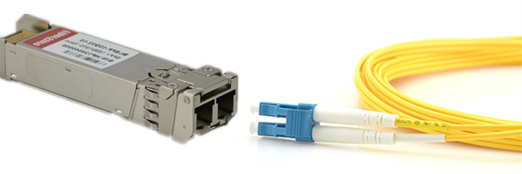
  • HP 1000BASE-LX SFP: HP 1000BASE-LX SFP transceiver, like HP J4859C, is specified to work over a distance of up to 10km over single mode fiber and it can also run over all common types of multi mode fiber with a maximum segment length of 550m. For link distances greater than 300m, you must install a mode-conditioning patch cord between the transceiver and the MMF cable on both ends of the link.
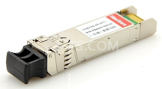
  • HP 1000BASE-SX SFP: HP 1000BASE-SX SFP transceiver, like HP JD118B, is compatible with the IEEE 802.3z standard and operates multi-mode fibers link up to 550 m. HP 1000BASE-SX SFP transceiver module consists of three sections: a VCSEL laser transmitter, a PIN photodiode integrated with a trans-impedance preamplifier (TIA) and MCU control unit. It is often applied for Fibre Channel links, Gigabit Ethernet links, Fast Ethernet links, etc.
Applications of HP 1000BASE SFP Transceivers

HP SFP Transceivers are designed to support SONET, gigabit Ethernet, Fibre Channel, and other communications standards. Storage interface cards, also called HBAs or Fibre Channel storage switches, also make use of these modules, supporting different speeds such as 2Gb, 4Gb, and 8Gb. Because of their low cost, low profile, and ability to provide a connection to different types of optical fiber, SFP provides such equipment with enhanced flexibility.

Conclusion

As a professional manufacturer and supplier for optical fiber products, FS.COM provides a wide range of compatible SFP transceivers branded by many famous companies, like Cisco, HP, Juniper, and Brocade. All these fiber transceivers are 100% compatible with major brands like Cisco, HP, Juniper, Nortel, Force10, D-link, 3Com, etc. Besides, these 1000BASE SFP transceivers are with high quality and backed by a lifetime warranty.


Higher Speed Transmission With Parallel Optics

2016-07-28 17:02:01 | Fiber Optic Transcei

Parallel optics is a term representing both a type of optical communication and the devices on either end of the link that transmit and receive information. Compared with traditional optical communication, parallel optical communication employs a different cabling structure for signal transmitting aiming at high-data transmission for short reach multimode fibers that are less than 300 meters. Traditional fiber optic transceivers cannot satisfy the increasing demand for high speed transmission, like 40GbE, while parallel optics technology can be a cost effective solution for 40/100GbE transmission.

MC2210411-SR4E

Comparison between parallel optics technology and the traditional serial optical communication would better explain what parallel optics is and the reason why it is a cost effective solution to high data rate transmission. The following of this article will offer the comparison between the two optical communication technology from two aspects: connectivity method and key components.

Connectivity Method

Literally, parallel optics and serial optics transmit signals in different ways. In traditional serial optical communication, on each end of the link, there are one transmitter and one receiver. For example, the transmitter on End A communicates to the receiver on End B, sending a single stream of data over a single optical fiber. And a separate fiber is connected between the transmitter on End B and the receiver on End A. In this way, a duplex channel is achieved by two fibers.

While in parallel optical communication, duplex transmission is achieved in a different way. A signal is transmitted and received through multiple paths, thus, the parallel optical communication can support higher data rate than the traditional optical communication. This is because, the devices for parallel optic communication on either end of the link contain multiple transmitters and receivers. For instance, in 2010 IEEE 802.3ba approved the 40GBASE-SR4 physical-medium-dependent multimode parallel optical solution, which uses eight fibers to transmit four duplex channels each at 10 Gigabit Ethernet. In this case, four 10Gbps transmitters on End A communicate with four 10Gbps receivers on End B, spreading a single stream of data over four optical fibers at a total data rate of 40Gbps.

Key Components

The parallel optical communication transmitting signals over multiple fibers, which has great advantages over traditional serial optical communication. It also means that it requires different components to support its high data rate transmission.

Connector — As previously mentioned, duplex transmission in serial optical communication uses 2-fiber duplex connectors, like duplex LC connectors to link the optics with other devices, while in parallel optical communication, multi-fibers are used to reach a higher data rate. Thus, multi-fiber connectors, like 12-fiber MPO connectors are used to connect with other devices. MPO connector is one key technology support parallel optical communication. This connectivity method is showed in the following picture (Tx stands for transmit; Rx stands for receive).

12-fiber-MTP-parallel-connection

Optical transceiver light source — Another complementary technology for parallel transmission is the light source of parallel optics—VCSELs (Vertical Cavity Surface Emission Lasers). Comparing with the edge-emitting semiconductor lasers in the traditional optics, VCSELs have better formed optical output which enables them to couple that energy into optical fibers more efficiently. In addition, VCSELs emit from the top surface, they may be tested while they are part of a large production batch (wafer), before they are cut into individual devices, which dramatically lowers the cost of the lasers. The following chart is about the comparison between VCSELs and edge-emitting semiconductor lasers. Cheaper to manufacture, easier to test, less electrical current required, supporting higher data rate, parallel optics using VCSELs could be a better choice to reach 40/100GbE transmission compared with traditional serial optics.

Parallel Optics for 40/100GbE Transmission

IEEE has already included physical layer specifications and management parameters for 40Gbps and 100Gbps operation over fiber optic cable. Two popular parallel optics solutions for 40Gbps and 100Gbps over multimode fibers are introduced here. For 40G, 40GBASE-SR4 transceiver is usually used, which requires a minimum of eight OM3/OM4 fibers for a transmit and receive link (4 fibers for Tx and 4 fibers for Rx). 100GBASE-SR4 transceiver (eg. QSFP-100G-SR4) is for 100Gbps transmission, which works through 4x25Gb/s 850nm VCSEL-based transmitter to achieve maximum link length of 100m on OM4 multimode fiber.

Conclusion

Parallel optical communication uses multiple paths to transmit a signal at a greater data rate than the individual electronics can support. Parallel transmission can either lower the cost of a given data rate (by using slower, less expensive optoelectronics) or enable data rates that are unattainable with traditional serial transmission. The capabilities and uses of parallel optics and MPO technology continue to evolve and take shape as higher-speed fiber optic transmission, including 40/100GbE. It is uncertain that parallel optical communication would be the trend in the future.


User's Guide To Third-Party Fiber Optic Transceivers Installation

2016-07-21 15:12:09 | Fiber Optic Transcei

Are you still hesitating to use third-party fiber optic transceivers? Maybe you haven’t noticed that the third-party ones are already predominant in the telecommunication market. Installing third-party fiber optic transceivers is relatively easy, providing you are using a transceiver that is MSA compliant and compatible with your brand of networking equipment. The following guide explains how to install third-party fiber optic transceivers:

1) Make sure you have the correct transceiver module for your device. Your device manual should contain a list of compatible transceiver models. The third-party transceiver module you purchase should also indicate which name brand manufacturer it is compatible with. For example, Fiberstore’s AFBR-79EEPZ QSFP+ transceiver is 100% compatible with Avago’s AFBR-79EEPZ. And their Cisco Linksys MGBT1 is 100% compatible with Cisco’s MGBT1.

2) Make sure you have the correct equipment and safety gear, such as a grounding device (e.g. ESD-preventative wrist strap), to prevent electrostatic discharge from damaging sensitive transceivers. If set down, fiber optic transceivers should be placed on a clean and static-free area, such as an antistatic mat.

3) Ensure that both the device’s transceiver ports and the transceiver’s plugs are clean and free of dust or oxidation. If the transceiver is new and won’t be used immediately, do not remove the dust plug. The dust plug at the end of a transceiver should only be removed at the time a fiber optic cable is inserted, and fiber optic cables should only be plugged into a transceiver after it is completely installed.

4) Properly orient the transceiver with the device slot. If your transceiver has a bail clasp (locking handle), pull it down until it clicks into a horizontal position. When installing a transceiver into a top slot, the bail clasp will typically be facing up when the transceiver is installed and locked into place. When installing transceivers into bottom slots, the bail clasp will typically be facing down when the transceiver is locked into place. Different devices can have different module socket configurations, so make sure you install the transceiver with the correct clasp-up or clasp-down orientation. For SFP and SFP+ transceivers, look for TX (transmit direction) and RX (receive direction) markings, or arrowheads, which will help you identify the proper orientation for the transceiver. Unnecessary removal and insertion should be avoided to prevent damaging both the transceiver and the device.

transceiver-graphic

5) When you slide the transceiver into the device slot there should be an audible click to indicate that the transceiver is in place. Press the transceiver firmly in using your thumb. To ensure the transceiver is secure, lightly tug on it and try removing the module without releasing the bail clasp.

transceiver-insert

6) If installing more than one transceiver, repeat steps 1-5 until all transceivers are installed. After all transceiver modules have been inserted, it’s time to remove the dust plugs on any cable-ready modules and begin connecting fiber optic cables. It is recommended that you remove the dust plug on the fiber optic cables first, and inspect and clean the end-faces of the connecting cables. Then remove the dust plug on the transceiver just before the cable is plugged in. This will keep the sensitive components inside your third-party fiber optic transceiver module protected as long as possible.

Learning how to install fiber optic transceivers is very helpful even though you are not a professional telecom engineer. As long as you follow the six steps outlined above, you should be able to install most form-factors of third-party transceiver modules without any hitches. For XENPAK compatible transceivers, you will need a flathead screwdriver to tighten the installation screws in the transceiver’s faceplate into the faceplate of the connecting device.


How to Classify Fiber Optic Transceivers

2016-07-15 15:23:55 | Fiber Optic Transcei

With the technological advancements in fiber optic communication, service providers tend to choose fiber optic to achieve high-level data transmission. Fiber optics generally offer users higher bandwidth, more reliable data transfer and better overall performance, thus enabling a smooth and excellent communicating experience. Fiber optic transceiver, which is considered to be the core of optoelectronic device in the WAN, MAN or LAN infrastructure, plays an indispensable part in fiber optic networks for data communication and Ethernet applications. This article will explain how fiber optic transceivers are classified according to different criteria such as fiber mode, transfer rate and connector type.

Fiber Optic Transceiver Overview

First of all, let’s take a quick glimpse of what fiber optic transceiver is and how fiber optic transceiver works.

455883-B21

Fiber optic transceivers combine a fiber optic transmitter and a fiber optic receiver in a single module. They are arranged in parallel so that they can operate independently of each other. Both the receiver and the transmitter have their own circuitry and can handle transmissions in both directions. In fiber optic data links, the transmitter converts an electrical signal into an optical signal, which is coupled with a connector and transmitted through a fiber optic cable. The light from the end of the cable is coupled to a receiver, where a detector converts the light signal back into electrical signal. Either a light emitting diode (LED) or a laser diode is used as the light source.

Common Classification Methods

The classification of fiber optic transceiver falls into various categories based on their performance characteristics and end-use. Classified by characteristics, they often include: fiber mode, transfer rate and connector type.

Fiber Mode
Fiber mode is the most fundamental classification of fiber optic transceivers, here the “mode” refers to the type of fiber intended to be used with a transceiver. The two primary types of fiber mode types are single-mode fiber and multimode fiber.

Multimode fibers allow multiple modes of light to couple into the fiber. Since multimode applications are always short reach, very inexpensive transmitters and receivers are typically used in multimode transceivers. As shown in the table below, there are several popular types of multimode fibers in use today. OM1 and OM2 fibers are appropriate for low speed transmission, such as 100 Mbps to 1 Gbps, which often utilize LED transmitters. OM3 and OM4 are referred to as laser-optimized multimode fibers, as lasers are used as optical sources at 10Gbps and faster. For example, Cisco Meraki MA-SFP-10GB-SR transceiver can achieve 300 meters over OM3 multimode fibers.

Single-mode fibers, however, only allow a single mode of light to couple into the core. The most common type of single-mode fiber is termed “OS1” by the ITU and is also known as “standard single-mode fiber”. So most optical transceivers are simply specified for operation over OS1.

Transfer Rate
Fiber optic transceiver modules also can be categorized by their data transfer rates. There are five popular rate categories used in fiber optic transceiver classification: 100GBase, 40GBase, 10GBase, 1000Base and 100Base. These rates refer to the speed at which a fiber optic transceiver is able to transmit data over Ethernet.

  • 100GBase—100 Gigabits per second (100GE, 100GbE, 100Gbps)
  • 40GBase—40 Gigabits per second (40GE, 40GbE, 40Gbps)
  • 10GBase—10 Gigabits per second (10GE, 10GbE, 10Gbps)
  • 1000Base—1 Gigabit per second (1GE, 1GbE, 1Gbps, 1000Mbps)
  • 100Base—100 Megabits per second (Fast Ethernet, FE, 100Mbps)

Connector type
Optical fiber connectors couple and align transceivers so that light can pass through the core. Based on their connector types,transceiver modules can be classified into different groups. There are four main types of fiber optic connectors used in conjunction with optical transceivers: SC, LC, MPO, and ST.

Connector types generally follow a color code system. If a boot is used over the connector, then a blue boot symbolizes compatibility with single-mode fiber and a beige boot symbolizes compatibility with multimode fiber.

Conclusion

Choosing which type of fiber optic transceivers mainly depends on your applications and requirements in reality. FS.COM offers you a full range of optical transceivers, such as SFP+ (SFP Plus) transceiver, X2 transceiver, XENPAK transceiver, XFP transceiver, SFP (Mini GBIC) transceiver, GBIC transceiver, CWDM/DWDM transceiver, 40G QSFP+ & CFP, 3G-SDI video SFP, WDM Bi-Directional transceiver and PON transceiver. All these fiber optic transceivers are 100% compatible with major brands like Cisco, HP, Juniper, Nortel, Force10, D-link, 3Com. They are backed by a lifetime warranty, and you can buy with confidence.


Selecting 10G SFP+ Optics Modules and Patch Cables

2016-07-13 14:51:11 | Fiber Optic Transcei

Nowadays, 10G connection in telecommunication network is gradually moving from the backbone to layer 2 and layer 3. Both technology and market of 10G optics modules are mature: the 10G optics modules have advanced from XENPAK which is the first generation of 10G transceiver to SFP+ which is now the most popular 10G optics. In addition, the price of 10G modules is getting lower. 10G modules are becoming affordable. Some genius guys even buy 10 SFP+ modules or SFP+ cable online to DIY private point to point 10G network. This article will offer basic information about 10G SFP+ optics modules and their connection instructions.

Basic of 10G SFP+ Optics

10G SFP+ transceiver has the same form factor of Gigabit SFP transceiver. Thus, many SFP+ modules can support 1/10G data rate to increase its flexibility during practical using. A SFP+ transceiver usually has two LC ports (as shown in the following picture). While 10G BiDi SFP+ transceiver, which transmitting and receiving signals from the same fiber optic cable, only has one LC port.

10G-SFP-duplex-patch-cable

Apart from fiber optic transceivers, there are also various factory terminated copper-based or fiber optic based cables which are terminated with a SFP+ module on each end of the cable. There are mainly three types of these 10G cables: 10G SFP+ passive direct attached copper cable (like HP J9283B), 10G active direct attached copper cable and 10G SFP+ active optical cable. These 10G cables eliminate the used of additional patch cable and can be directly plugged into the SFP+ ports on switches. It is acceptable that these cables are an cost-effective and reliable solutions for 10G connections in short distance.

Optical Standards of 10G SFP+ Transceiver

According to IEEE standards, there are a variety 10GBASE SFP+ transceivers. For short distance transmission, 10GBASE-SR SFP+ and 10GBASE-LRM SFP+ can support transmission distance up to 300 meters and 220 meters over multimode fiber optic cables separately. 10GBASE-SR SFP+ modules is the most commonly used transceiver for short distance. It is suggested to work over wavelength of 850 nm.

There are a lot of 10G SFP+ transceivers that support long distance, like 10GBASE-LR SFP+, 10GBASE-ER SFP+, 10GBASE-ZR SFP+, CWDM SFP+, DWDM SFP+, BiDi SFP+, etc. These transceivers can support transmission distances ranging from 10 km to 120 km over single-mode fiber optic cables.

There is another special type of 10G SFP+ transceivers which has been mentioned in this post, which is known as dual-rate SFP+. For example, dual-rate 1000BASE-LX and 10GBASE-LR SFP+ transceiver can be adjusted to support both 1G and 10G data rate up to 10 km over wavelength of 1310 nm.

bidi-10G-transceiver-simplex-cable

Fiber Patch Cable Selection Guide for 10G Transceivers

As 10G SFP+ DAC and AOC eliminate the using of additional patch cords. This part will introduce the selection guide for 10G SFP+ transceivers. During the selection of fiber optic patch cables for 10G transceivers, the transmission distance is the first element to be considered. Single-mode patch cable is used for long distance transmission and multimode is designed for short distance transmission. Then the ports on the transceiver for receiving and transmitting should be considered. As mentioned, most 10G SFP+ transceiver use duplex LC port, while BiDi SFP+ use simplex port. Thus, simplex LC patch cords or duplex LC patch cords are used according to the port type on the transceiver.

Conclusion

Although newer standards for higher speed, like 40Gbps and 100Gbps have already been launched, it can still be predicted that, 10G connections especially the SFP+ based optics and cables are bound to continue to dominate the market for the next 10 years or more.